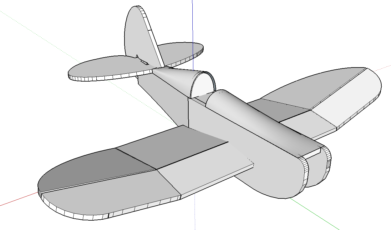
[Plugin][$] Curviloft 2.0a - 31 Mar 24 (Loft & Skinning)
-
How? What? Which part isn't clear?
You have yourself listed in your profile as Advanced, it is assumed therefore that you know the basics. Could you clarify your sketchup level so we know how to answer your questions.
-
Nevermind, I'll ask somebody else.
-
From the picture it looks like a moonscape and you are trying to put a smooth flat floor in a crater. If so, then the floor perimeter does not seem to have to be very accurate.
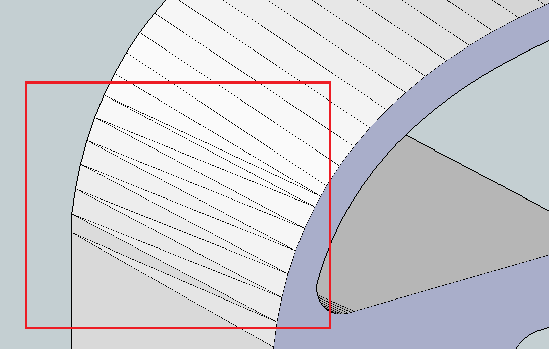
Given that, then this is a modified solution I use to fix the jaggies on fairings after an intersect of curved surfaces. BUT it is a fair bit of work.Also I think you encountered an operational problem with Curviloft I get when trying to skin a flat(ish) surface on a complex perimeter. My usual solution follows as well (3).
But wait..... There's more, a quick and dirty way to give those craters a flat floor.
1-Create a face (rect or circle) just below the hole and group it. Move it up to just meet the lowest point of the hole perimeter. SU will tell when that occurs with a constrained flag.
Then move it up to just past the highest endpoint of the perimeter.
Explode the flat face, select all the touching faces of the crater and floor and intersect.
You can delete the outside of the crater base and any bits hanging down if you want.
If the crater base disappears then undo till it reappears and leave it as so.2-As above, create a grouped face below and bring it up to the lowest point.
With the move tool grab an endpoint of the hole perimeter, hit the alt key then the down arrow and move the endpoint down to the grouped face. When SU says it is constrained, let go.
Do this for each endpoint around the hole perimeter.
Explode the flat face. If you got all the points, a crater floor will result. As above, delete the extra bits or not.3-When CL stubbornly refuses to create a face, select the perimeter lines, as best you can. If some other lines and faces are selected as well, just ignore them for now.
Make the selection a group temporarily. Copy it and move it on any one axis away. It is just easier to work with, out of position.
Edit the group and start deleting all unwanted lines and faces that are not specificly the crater floor perimeter.
CL the perimeter.
If it fails, that means you have tiny gaps and/or line fragments in the perimeter. Clean those up and try again.
If it works, delete the original floor perimeter group, then move the fixed floor perimeter group back on axis to its original position and explode it.
Then cleanup the opened faces by redoing the triangles, endpoint to endpoint.
Do not accept a constrained endpoint, you need a real endpoint.And if that doesn't work you need to post your model here and someone will help fix it.
But that will not be me as I am in Singapore and without my Sketchup computer, unless you can wait till mid Nov when I get home. And all my replies are time lagged 12 hours to Eastern time.
-
Select: Draw a selection box laft to right over the area you want and it will select everything wholly within that area or right to left and it will select everything the box touches.
Smooth: Right click on your selection and select Soften/Smooth from the context menu and adjust settings to suit.
Knowing how to answer a question is quite difficult some times. We need to look at the few clues available to understand how much detail needs to be given. If the question is from a beginner in the newby section then I would be very clear about how to do something but a question from an Advanced use in the plugin section makes you think I don't need to spell it out.
-
@jgb said:
From the picture it looks like a moonscape and you are trying to put a smooth flat floor in a crater. If so, then
Thank you, you gave me a couple of amazing ideas!
I attach the demo file. The full file is 27MB, I'll try uploading it somewhere...

-
Looks like canì't atttach a skp file...
-
@jumpjack said:
Looks like canì't atttach a skp file...
There is a file size limit to attachments. You could make a separate file of just a small portion of the overall model. It won't take the whole thing to explain what needs doing.
-
I decided to upload the whole file, in case others in the world are interested in some archeo-astro-photogrammetry

http://jumpjack.altervista.org/mars-pathfinder-model-D-color.zip (43 MB)
Project page:
http://www.boards.ie/vbulletin/showthread.php?t=2057032501 -
I don't think there is anything out there to heal your model. I have no idea how it was created, do you have individual files of each photometric section, but you have overlapping sections in a radial array and a mass of jagged bits and loose geometry all over the place. Maybe you can repair each part of the radial array in meshlab then stitch them together. Plus you seem to have multiple copies of the component which is making the file much bigger than it needs to be.
What is it you want to end up with? Is it something you want to print? Is it meant to be an accurate Mars landscape? Is it just going to be a rendering?
You can quickly sculpt a nice landscape with the Sandbox tools to form a printable solid or basis for a render.
The one below took minutes to make. There is nothing stopping you making it as detailed as you want and starting with a solid mesh means you have no holes to fill. You can also use Fredos ThruPaint to place your images correctly.
None of this really has much to do with Curviloft so it would probably be more appropriate moved to it's own thread.
Also there are several plugins designed for working with topography, Toposhaper for one, that may be more suited to your project. http://sketchucation.com/forums/viewtopic.php?p=470701#p470701
Or perhaps some point cloud plugin if the photometric data is suitable.If this is something like you want I can give you more information.
Edit: I looked at your project page and now I have some understanding of what you are attempting. If you can get the point data I'm sure there is a way to get close.
-
@box said:
Edit: I looked at your project page and now I have some understanding of what you are attempting. If you can get the point data I'm sure there is a way to get close.
I didn't have a look, but after reading this, I have thought about this:
https://www.youtube.com/watch?v=092ZzSrsE_w -
@box said:
I don't think there is anything out there to heal your model. I have no idea how it was created, do you have individual files of each photometric section, but you have overlapping sections in a radial array and a mass of jagged bits and loose geometry all over the place.
Yes, it's a mess...
@box said:
Maybe you can repair each part of the radial array in meshlab then stitch them together.
Maybe I could fill holes in each part using this plugin(it works fine for simple holes) and also stitch them together using the plugin again. Hopefully this will result in new holes which I will maybe be able to fill using again the plugin... and so on till I fill all of them!
@box said:
Plus you seem to have multiple copies of the component which is making the file much bigger than it needs to be.
I didn't notice it, I'll check.
What is the attachment?
-
@jumpjack said:
What is the attachment?
It is a simple sandbox model with a random mars landscape as a texture, and the rover roughly lifted from your model and dropped on it.
-
**I love this plugin, especially the splice feature.
Does anyone know of another similar feature that creates a grided planar surface in a similar effect- to that of the black mesh that appears in modeling before it generates a smooth surface?!
Thanks!**
-
At any time you can make any 'smoothed surface' into a 'mesh', with fully visible edges, by selecting the surface and using the native 'Soften/Smooth Edges' tool [context-menu], with minimal angle-slider setting and the two options ticked...
Of course you can do the reverse [on any 'mesh'] - select all of the facets required and move slider to right so the surface becomes smooth...
-
And what Tig has modestly left out, a lot of his plugins allow you to choose quads, if that is the full square grid you are after.
-
Great Thanks!
-
This tool did exactly what I needed! Great work!

-
Could this plugin be adapted into a new/similar plugin but for sheet metal fabrication? With some of the functions described here in this SolidsWorks video; in particular bend lines and flattening functions?
-
thankk you very much ^^
-
Thank you for this amazing plugin.
I am trying to use the outcome of the Curviloft for hotwiring foam (with CNC) for RC airplanes.
My problem is that the some of the faces created are triangular - which is great for the purpose of lofting in SU, but is not good for hotwiring. If I use the path of triangles, the speed of the wire will not be constant on both faces.Anyway, my question is:
Is there a way to make Curviloft create only quadratian faces?
Thanks,
Rony
Advertisement


