Cutting through component?
-
Hi,
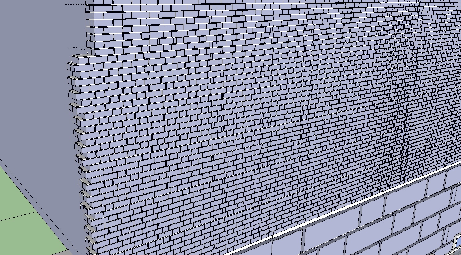
I'm trying to create a building with a brick exterior, so to save myself some time I imported pre-made brick model from the 3D warehouse. However, now I need it to line up on the sides and cut through it to add windows (image attached).
Is there anyway I can do this quickly? I tried to add windows by using intersect but that didn't do what I wanted.
Any suggestions?
Thanks!
-
This has to be done manually.
You are making an incredibly complex and heavy model with little benefit
Using a simple 3d wall box would be easier to cut with a hole.
You could then apply a well made textured material [drawn as brick sizes] on the wall's face and position it using the context-menu Texture tools so it starts at an edge.
You can see if the opening aligns with the texture's pattern...Incidentally, if you go down the route of the individual bricks your coursing pattern is a type that disallows simple holes by deletion and adding half-bricks at reveals, because it has headers and will need 'quarter-bats' to work properly at reveals etc... An example of how not to course it is in the top left of the image, where you have all of the perpendicular [end] joints stacked one above the other

-
+1 to what TIG says.
The only time I would go to that level of modelling would be to show a localized assembly detail. For building construction I would typically limit that to what fitted in a 1m cube.
P.S. If you are detailing, 2D is still a valid graphic presentation technique; expecting the whole building model to show everything is not a realistic prospect yet!
-
You might want to get on the face orientation thing and correct all those reversed faces before you get much farther along in your model. They are likely to cause you headaches later.
Hello! It looks like you're interested in this conversation, but you don't have an account yet.
Getting fed up of having to scroll through the same posts each visit? When you register for an account, you'll always come back to exactly where you were before, and choose to be notified of new replies (either via email, or push notification). You'll also be able to save bookmarks and upvote posts to show your appreciation to other community members.
With your input, this post could be even better 💗
Register Login


Advertisement