[Plugin] Center of Gravity
-
It is NOT the Composite tool that's the issue.
Because if you notice, the two 'motor's' CofG's have 0 weight returned anyway !
This is probably because the two selected objects are too complex, and are not 'solids' and probably have internal partitions, single planes etc.
If you make a simple grouped solid cylinder the same size as the 'motor' you should get a proper a weight and a true CofG for it...
Of course none of this is definite because you haven't supplied the SKP in question...

-
Here's v1.6
http://sketchucation.com/forums/viewtopic.php?p=229401#p229401
1.6 20130209 Intersection gaps caused by tiny facets healed to improve accuracy.
Volume is now exact if it's a solid or best approximation otherwise.
Accuracy option added: default is 1%, note that making if lower will dramatically slow things down, more that 5% could be inaccurate on some complex forms.
The lingvo files have been updated to suit. -
I did not expect to see a tool like this available for SU. TIG, you continue to astound and amaze us. Thanks!
-
Hi TIG,
Great plugin, but I'm having a bit of a trouble getting Composite C of G to work. It is probably just user error!
I select two previously made CofG groups (different group names, same density). I get no errors, but no Composite C of G either. Ruby console has the following:
Error: #<NoMethodError: undefined method
entities' for nil:NilClass> /Library/Application Support/Google SketchUp 8/SketchUp/Plugins/CofGravity.rb:649:indo_composite'
/Library/Application Support/Google SketchUp 8/SketchUp/Plugins/CofGravity.rb:116:ininitialize' /Library/Application Support/Google SketchUp 8/SketchUp/Plugins/CofGravity.rb:816:innew'
/Library/Application Support/Google SketchUp 8/SketchUp/Plugins/CofGravity.rb:816
/Library/Application Support/Google SketchUp 8/SketchUp/Plugins/CofGravity.rb:649:in `call'
/Library/Application Support/Google SketchUp 8/SketchUp/Plugins/CofGravity.rb:649I'm on a MacBook Pro running 10.7 using SketchUp 8 and CofG v 1.6. I'm also in the process of learning Ruby, but am as yet a novice, especially Ruby with SketchUp.
I know you have probably moved on to other things by now, but a hint on any changes would be great!
thanks,
mark -
Are the CofG groups intact with all of their contents etc as originally made.
Maybe there's some text missing ?
Can you post the SKP ?
Or PM it... -
Tig
CofG has become a MUST Have for me lately. I am starting to map out the CofG for a few hundred groups and components on 2 major aviation models. Grouping helps but I have a serious need for an improvement to CofG.
Some background......
To compute the CofG for an airplane, I need to locate each of the components CofG in relation to a common point of origin, called the "Datum Zero" line, which is almost always the nose tip, but could be offset fore or aft of that. Multiply the distance from that origin to the CofG for that component gives a moment arm value. Sum all the moments values and divide by the total weight gives the airplanes center of gravity, which has to lie very close to the center of lift.Then calculating the variables of fuel, payload, etc and the control surfaces ability to vary the center of lift gives me the operating envelope, or an indication of what needs to be moved to put the CofG and CofLift within the operating envelope.
Right now I have to measure the offset of the CofG from the components most forward point, and the distance of that forward point from Datum Zero. Those values, and the components weight go into an Excel spreadsheet. A significant problem is when my components bounding box is rotated away from normal, making the finding of the most forward point difficult.
Grouping helps but I have a serious need for an improvement to CofG.
 Would it be possible to map the components CofG offset (X-Y-Z) from the SU axis origin point, as an option?
I can then place the models Datum Zero on the SU Axis Origin point, and it would vastly simplify my task. I would only need to enter the offset and weight into my Excel sheet, and not have to measure anything.
Thanks.
-
Have you considered moving the axes of your components ?
Select an instance and right-click context-menu Change Axes...
That way you can ensure that all axes are sensible arranged, making other tasks easier...
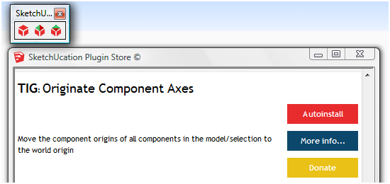
I also wrote a tool to move all selected components' axes to the model-origin...
Perhaps using that will do what you want ?
-
Hadn't thought of that, but, in my case it won't work. I have many of the same component strung out along the length and breadth of the aircraft. These would be skin panels, frames, passenger seats, washrooms, etc, as well as structural parts and equipment. So moving the components origin to the SU origin is unworkable. It would also make the bounding boxes so large that it would be a visual nightmare trying to select individual components with all the overlapping bounding boxes. It would also require me to change the comps axis position every time I moved the comp.
Also, changing the comps local axes point won't help either, especially when the comp is rotated a bit in final placement. Regardless of rotation, I will still need to measure every components location of its most forward point from Datum Zero and then measure its CofG offset from that point as well.
If your CofGravity.rb could measure the distance from SU origin in X-Y-Z (Green-Blue-Red) to the comps computed CofG then that would eliminate any measuring and would give me a more accurate moment offset.
CATIA does this moment offset (distance from Datum Zero to CofG of part) automatically and generates the moments table as the parts are defined (as solids with material defined). The table is dynamic, so if parts are moved, the CofG of the airplane is updated in real time, but then CATIA is purpose designed for aerospace and costs $35,000++ a seat. A bit too rich for my blood.

-
Can't you use Xray mode, then a tool like my 'Coords Text Tag from Datum' http://sketchucation.com/forums/viewtopic.php?p=284829#p284829to add the XYZ in the model, set from the Origin as the datum OR you could set any other 3d point as the datum... The tag can be relocated to any point and gives the current XYZ values, you can also tailor how the numbers are shown...
-
Looks like it should work for me.
I'll try it later today or tomorrow and report back here. -
Tig Re: Coords....

It seems to do what I need, but I have a few questions about some of the dialogs, which I will post in Coords post.
All I need to say here is, Please think about combining the XYZ coords part with the CofGravity Ruby
I would think that the hard part of coding has been done, and all you really need do is an integration and dialog box changes. I know it is not a trivial task, but a lot of the hard work has been done.
-
Thanks Tig! I end up doing some maritime related work at times with SU and C of G is excellently helpful. Just an idea... and I have no idea if it is its feasible, but a Center of Buoyancy plugin would be awesome too. I am trying to use the process shown at http://www.youtube.com/watch?v=HRJY-0Ryw6I for some buoys I am designing but in Sketchup Pro...and I think its working....not sure. I bet other SU maritime folks would love it too. Just a thought in case someone out there get interested.
-
@rbarone said:
Thanks Tig! ...... but a Center of Buoyancy plugin would be awesome too. I bet other SU maritime folks would love it too. Just a thought in case someone out there get interested.
The how-to video using Solidworks is similar to the way we used to have to do it in SU before TIGS CofG plugin.
Center of Gravity and Center of Buoyancy are equivalent for homogeneous solid constructs.
If you select the underwater portion of the model as a separate solid group/comp up to the waterline, then CofG is CofB, along either horizontal axis. Obviously, the volume displaced is the tunnage. And SU gives you wetted surface as well.
With some trial and error selection of wet hull sections at heel angles (to maintain approximately equal buoyancy at heel vrs upright) you can also determine both CofB and righting moment as well.
I've done it, but it can get tedious doing the slices.
I have also done it for sail plans, by giving the sails a slight artificial thickness to create a solid, then the GofG equates to center of pressure on the sail plan. A little arithmetic gives you your required keel weight at the rail down heel angle.
CofG is also very useful in placing various objects in the vessel, such as the engine, water and fuel tanks. Setting up an EXCEL spreadsheet makes this simple to play with re-locations to compute the overall CofG compared to the CofB. This goes for fixed components as well, such as the hull, deck, cabinetry and rigging. Just make everything solids and know their densities or actual weights.
-
Thanks jgb, much appreciated. C of G being the same as C of B makes sense to me. Question: how would you go about using SU to determine underwater portion? Would you do the same thing in the video or would it be everything below the C of G? I appreciate the advice very much.
-
One more thing....I am trying to work of the C of B of a simple spar buoy cylindrical in shape.
-
RBarone, I think I would do what you are trying to do in DelftShip or Free!Ship. You could get all the hydrostatic calculations done easily and accurately. If you want a SketchUp model of the buoy, that's fine but it probably makes sense to get the data you need from an application that is designed to do it.
Out of curiosity, how are you determining things like the waterline of the buoy?
-
I was using an existing larger concept model I found online and drawing a similar version in SU. Then scaling it down to a smaller size as a start, with the thought that the weighted portions, waterline, and buoyancy would scale down proportionately. I guess its pretty clear by now I am no naval architect. So any input or advice is well received. I was hoping I could determine the waterline as shown in the video clip mentioned above. I'll checking out DelftShip and Free!Ship now. Hopefully they let me make such a simple shape. If they calculate everything that would be great.
-
@rbarone said:
Thanks jgb, much appreciated. C of G being the same as C of B makes sense to me. Question: how would you go about using SU to determine underwater portion? Would you do the same thing in the video or would it be everything below the C of G? I appreciate the advice very much.
Obviously you need to know and be able to draw the buoys shape reasonably accurately in SU.
Then you need to know, calculate or estimate where the waterline should be on the shape. That would be the hard part, because the total weight of the buoy is far more than just the buoyancy chamber. Assuming you know the total weight, then a solid rendition of the SU model will give you the maximum floatation available, because SU will calculate the solid volume of the buoyant part.Then using a simple ratio of total buoyancy to total weight will give you a starting point to finding the waterline. Lets say for example, the weight is 60% of total buoyancy, then the waterline will be at 60% of the volume. That, like I said, is a starting point.
Make a note of that volume. That is the target you are shooting for. Entity Info will tell you that.
I don't know what level of expertize you have with SU, so I will explain in some detail what happens next. Ask for help if you need it.
-
Make sure you have a solid component of the buoyancy chamber.
-
Make a copy and move it away from the original. Make it "unique". That way you don't mess up the original which you may need several times over doing this.
-
Draw a square face larger than the expected waterline size on the buoy, and group it.
-
Move the grouped waterline face over the copy at about the 60% point. Make sure none of the buoys lines touch the edges of the waterline face. Make the waterline face larger if that is the case. It doesn't matter how big it is, just has to be bigger than the buoy.
-
Edit the unique buoy and select only the faces that touch or cross the waterline face. You can also "select all" of the buoys faces if you wish.
-
Do an "intersect with model". That will transfer a line where the waterline face crosses the buoy.
-
Now select only the portion of the buoy that is "below" this waterline and group it.
-
Edit this group, and select any line that is the waterline and "face" it. This will close the shape and form a solid. If it does not face, you have a missing fragment problem that happens often in SU.
 You will need to analyze every line and vertex on the waterline and fix those errors manually. Post the model here if you can't solve this, it can get hairpulling at times.
 -
Close the group and check the volume statistic in Entity Info. Compare it to the target volume.
-
If it is "close enough"
(you decide how much is close enough) then that IS your waterline.
Use CofG to find the center of buoyancy. -
If the volume is not close enough to target,
 then do a number of "Undo's" to return to where you were at step 5 before you edit. Or delete the buoy copy and get a new copy from the original, and again, make it unique. Then move the waterline face up or down a bit and repeat steps 5 to 10 till you are happy.
It is not as complex as you think. Steps 5 to 10 should take about 1 minute total, unless you have waterline gaps in step 8.
If you can't make that work for you, we can take it to the next level.
-
-
Ok, lets see how I did in the attachment. Please see attached and let me know if I am close on the C of B and C of G. If so, then I've got it. I am pretty sure I am grasping the concepts here. If I made a mistake, I suspect its got something to do with either including or not including the volume of the ballast section. I appreciate the help very much.
Work in progress - practice determining center of buoyancy with sketchup
-
Please save and re-post it in Ver 8 format. Then I can check it out.
Hello! It looks like you're interested in this conversation, but you don't have an account yet.
Getting fed up of having to scroll through the same posts each visit? When you register for an account, you'll always come back to exactly where you were before, and choose to be notified of new replies (either via email, or push notification). You'll also be able to save bookmarks and upvote posts to show your appreciation to other community members.
With your input, this post could be even better 💗
Register Login


Advertisement