What's the best way ?! [Organic Shapes - Buildings]
-
@thomthom said:
Rhino 5?
yeah.. (there is no rhino 4 for mac.. and actually, there's no official rhino 5 on mac either
 .. still a beta)
 -
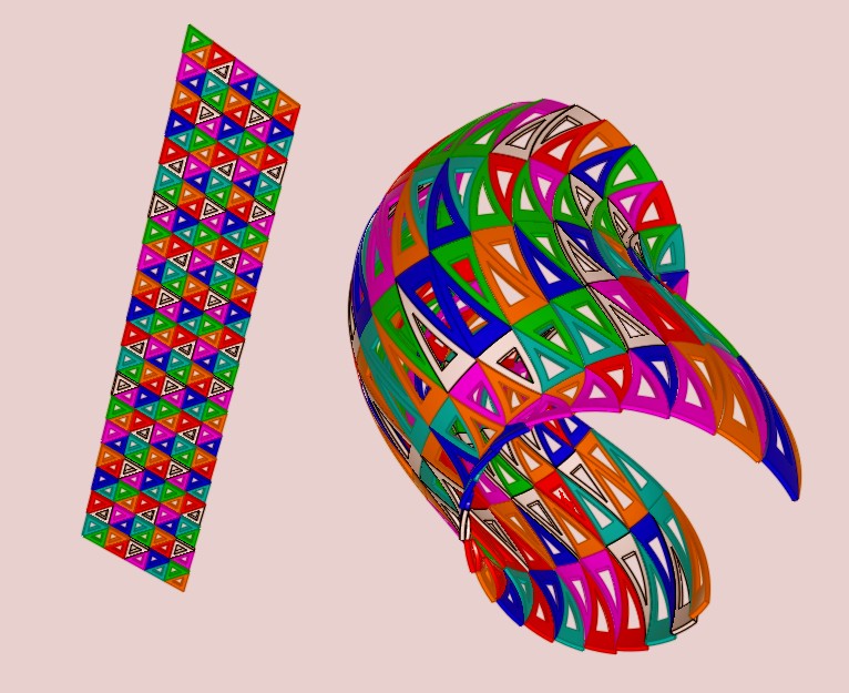
Or in Moment of Inspiration where you can project any volumes on an another tortured one!

Here my little triangles are not all in the same plan
so the circular "side" is slighty offseted
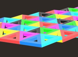
Colors are randomized on each volume!
Of course each triangle is deformed following the form!
-
@unknownuser said:
Or in Moment of Inspiration where you can project any volumes on an another tortured one!

yeah.. that's the same as flow along a surface in rhino.. doing that (obviously) distorts the shape to match the surface (i.e.- they are no longer triangles.)
paneling tools doesn't do that… in the drawing i posted above, all of the members of the triangles remain straight.. it's only the length & angles that change in order to fill the grid..
-
Yep, i must just rotate source(& size) and target on the good directions for have the same

PS Have you seen the little Conoïde membrane problem?
It's for you!
-
@unknownuser said:
PS Have you seen the little Conoïde membrane problem?
It's for you!
haha.. i haven't opened that thread yet.. and i better not -- i have some things to do today..
ok.. maybe just a peek
[EDiT].. same thing for that as this.. the conoid membrane is literally a 30 second deal in rhino and that's how i would draw something like that.. since this is a sketchup forum, i'll refrain from posting "use rhino for this" in yet another thread..

-
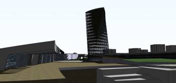
this is something in progress ...
the tall building isnt the same as i wanted to saw at dubai's picture
but all in all this is the sample of the mixed plugin i used.p.s. about the last rhino issue ... i knew i can make it easier in rhino
but im trying to chack sketchup limition
-
@unknownuser said:
distorts the shape to match the surface
In fact you right!

I must find another trick
Something like LineWeb / Planar = gride paneling
So my volume is "facettized", so the Flow function don't curvate the triangles!
-
@yitzhar said:
p.s. about the last rhino issue ... i knew i can make it easier in rhino
but im trying to chack sketchup limition
it's not that you can't draw this in sketchup (i mean, i've driven a nail with pliers before.. plenty of times
 )
)it's just that it's a fairly convoluted process to do it in sketchup and once you've drawn something, you're stuck with it.. and it's a whole lot of work to start over with this type of process until you get the proportions etc correct..
in all reality, my sketchup approach would go something like this:
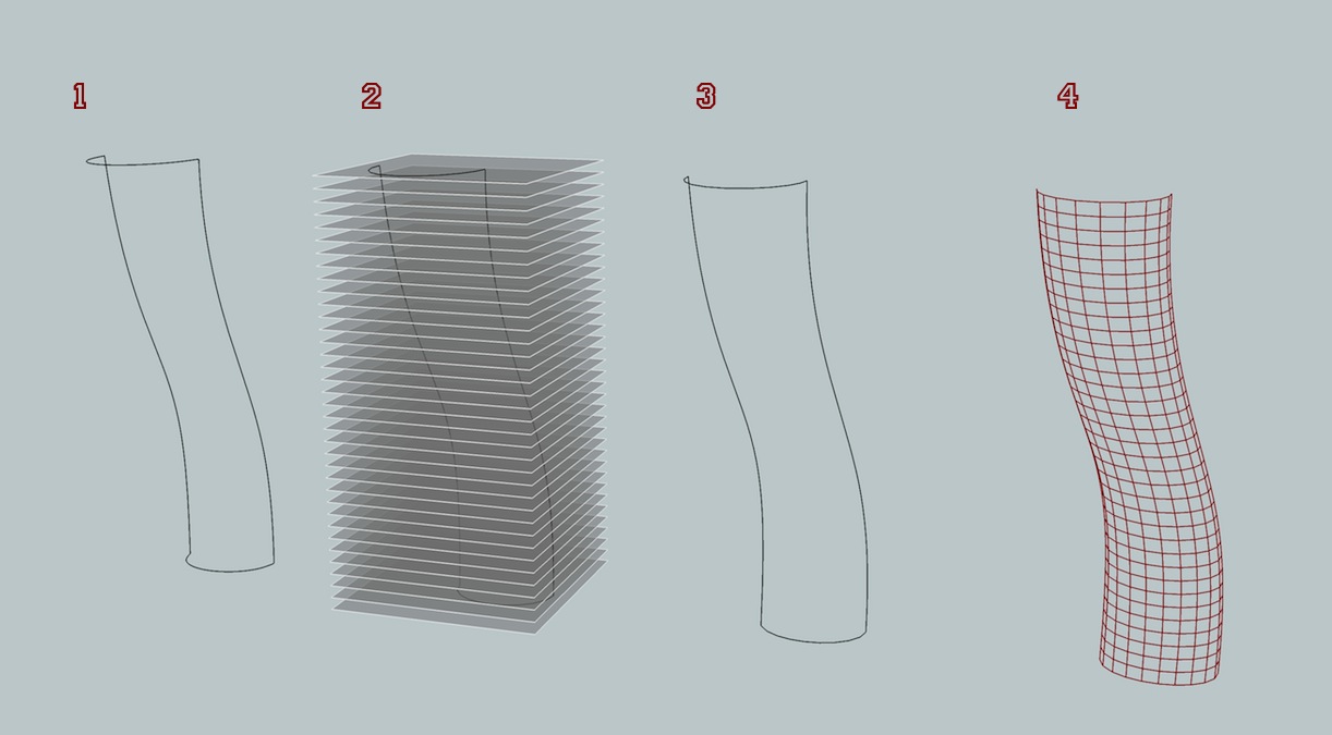
1)- draw the main profile curves with a whole bunch of segments per curve (the vertical profiles have 500 segments in this example) (i'm using fredo's BezierSpline plugin for these curves).. group the curves..
2)- array a plane to represent the floors... using the line tool, custom draw new profiles.. the vertices will occur at the intersection of each floor plane and the mega-segmented curves.. using BZ-convert to, change the top and bottom curves to the same amount of evenly spaced segments (i used 10 in this case)..
3)- while this looks pretty much the same as step #1, it's not.. the profile curves are now set up to make a proper grid on this shape..
4)- using CurviLoft's skinning function, set it to generate edges only... you now have a nice grid to place your panel profiles over..
5)- (next image) -- use profile builder to manually populate the grid.. only 30+ more floors to go then mirror it

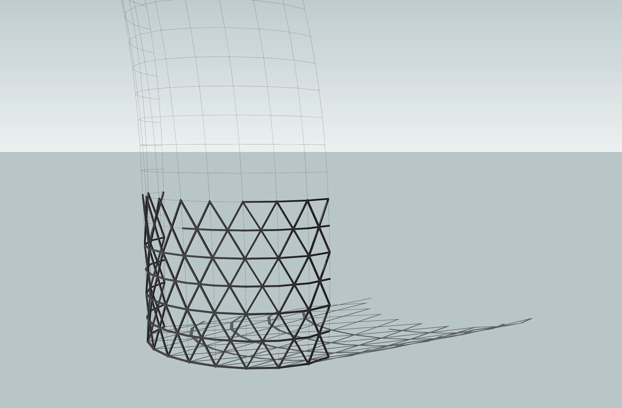
-
A very cool solution!

-
@unknownuser said:
@yitzhar said:
p.s. about the last rhino issue ... i knew i can make it easier in rhino
but im trying to chack sketchup limition
it's not that you can't draw this in sketchup (i mean, i've driven a nail with pliers before.. plenty of times
 )
)it's just that it's a fairly convoluted process to do it in sketchup and once you've drawn something, you're stuck with it.. and it's a whole lot of work to start over with this type of process until you get the proportions etc correct..
in all reality, my sketchup approach would go something like this:
[attachment=1:3nr0a3tj]<!-- ia1 -->pt.jpg<!-- ia1 -->[/attachment:3nr0a3tj]
1)- draw the main profile curves with a whole bunch of segments per curve (the vertical profiles have 500 segments in this example) (i'm using fredo's BezierSpline plugin for these curves).. group the curves..
2)- array a plane to represent the floors... using the line tool, custom draw new profiles.. the vertices will occur at the intersection of each floor plane and the mega-segmented curves.. using BZ-convert to, change the top and bottom curves to the same amount of evenly spaced segments (i used 10 in this case)..
3)- while this looks pretty much the same as step #1, it's not.. the profile curves are now set up to make a proper grid on this shape..
4)- using CurviLoft's skinning function, set it to generate edges only... you now have a nice grid to place your panel profiles over..
5)- (next image) -- use profile builder to manually populate the grid.. only 30+ more floors to go then mirror it

[attachment=0:3nr0a3tj]<!-- ia0 -->pb.jpg<!-- ia0 -->[/attachment:3nr0a3tj]
great way!

-
Seems Windowizer by Rick wilson makes the last number step 5 automatically ?
-
@unknownuser said:
Seems Windowizer by Rick wilson makes the last number step 5 automatically ?
hmm.. it's close but it wont allow you to define the pattern.. it just follows the same lines which make up the surface (in this case, curviloft triangulates the grid and with windowizer, it doesn't matter if i build the surface with pseudo quads or not.. )
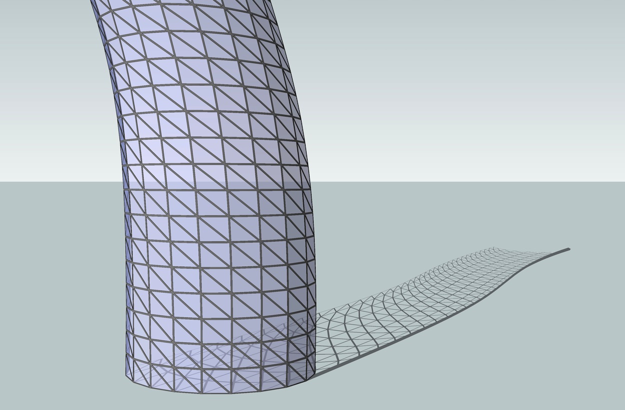
-
How must be the connection of the modules ? Perfectly pasted at the surface but "conic" toward the center of the building (like a joint PushPull) or strictly "squared" so "un pasted" in the external ?
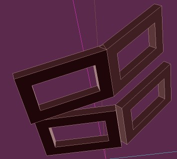
Next step will be a little more complex

By Jotero

-
@unknownuser said:
@unknownuser said:
PS Have you seen the little Conoïde membrane problem?
It's for you!
haha.. i haven't opened that thread yet.. and i better not -- i have some things to do today..
ok.. maybe just a peek
[EDiT].. same thing for that as this.. the conoid membrane is literally a 30 second deal in rhino and that's how i would draw something like that.. since this is a sketchup forum, i'll refrain from posting "use rhino for this" in yet another thread..

Jeff, Please don't refrain from comparing with rhino. Im learning it currently, and Im very interested to see how you attack these problems with Rhino. I've see it on a few threads. Im Very curious how to make the conoid membrane with Rhino. Im really quite new with it.
-
@pjbazel said:
Jeff, am I missing something your approach makes me feel like Im missing some essential detail or a technical consideration. Have i missed something?
how does it look? it sounds like it looks similar to the (incorrect)example i posted at the top of this page(3) whereas the picture posted in the original post has a pattern of alternating triangles... a pretty big detail both structurally and visually..
V^V^V^V^and not|\|\|\|\|(lol at me trying to draw the pattern using the keyboard)
[eDIT]-- oh.. and hey.. i'll be the first to admit, i'm usually pretty damn picky when it comes to detail..
(ie- most of the stuff i draw irl has to then be built.. i can't just draw a sort of shape then start pulling vertices around (ffd style) and say 'ok, that looks about right' then go try to build it.. that would be a nightmare build and it would more likely than not, collapse )
)so, when you see the sketchup method i posted on page 2, realize it's an attempt at making properly outlined geometry (systematic geometry? understandable geometry? idk) for building purposes as opposed to viewing purposes)
-
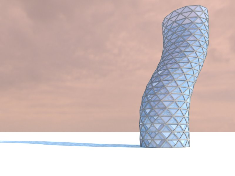
PS. I also took a run at this.
I used the same technique as gill to get the Basic shape.
Then I use lattice maker but with a depth of 0 to generate a lattice structure with windows (essentialy offset faces) - sure to assign separate colors/textures to the glass and lattice so you can 'select by color' later.
So, I have the 2d structure. From there I just used JPP to get the thickness of the lattice, selecting by color, pulling outward.
I finish the building with JPP, select by color and creative grouping and ungrouping to get proper depth and placement for windows, which are two pane and inset.
Jeff, am I missing something your approach makes me feel like Im missing some essential detail or a technical consideration. Have i missed something?
-
@Gilles
Réclamations!
The 2 files are V8!
-
@pjbazel said:
<added image>
 that looks nice..
@yitzhar.. do what bazel is doing.. it's a lot simpler than that path i'm trying to lead you down

-
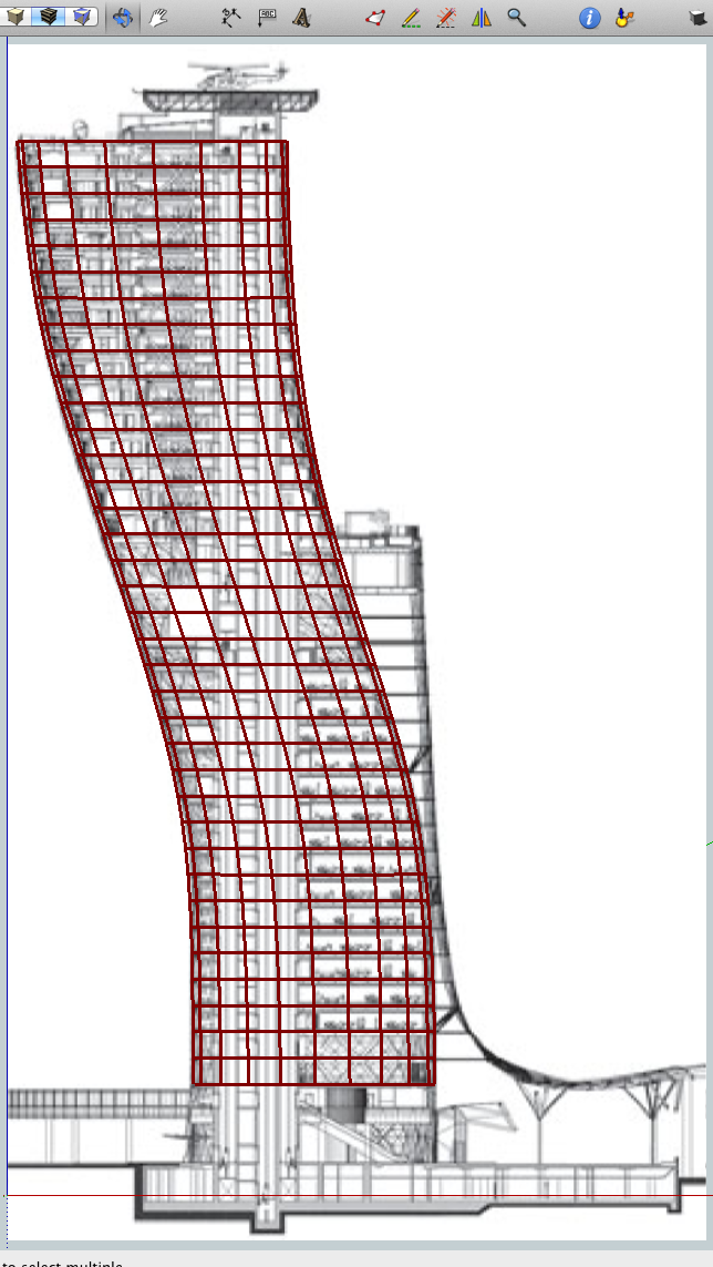
fwiw.. one reason why the approach i went after might seem longer than necessary was that i was trying to draw the actual building from the original post (within reason).. it wasn't until later in the thread that yitzhar said he only was after that style and not the building itself..
-
@unknownuser said:
@pjbazel said:
Jeff, am I missing something your approach makes me feel like Im missing some essential detail or a technical consideration. Have i missed something?
how does it look? it sounds like it looks similar to the (incorrect)example i posted at the top of this page(3) whereas the picture posted in the original post has a pattern of alternating triangles... a pretty big detail both structurally and visually..
V^V^V^V^ and not |||||
(lol at me trying to draw the pattern using the keyboard)
[eDIT]-- oh.. and hey.. i'll be the first to admit, i'm usually pretty damn picky when it comes to detail..
(ie- most of the stuff i draw irl has to then be built.. i can't just draw a sort of shape then start pulling vertices around (ffd style) and say 'ok, that looks about right' then go try to build it.. that would be a nightmare build and it would more likely than not, collapse )
)so, when you see the sketchup method i posted on page 2, realize it's an attempt at making properly outlined geometry (systematic geometry? understandable geometry? idk) for building purposes as opposed to viewing purposes)
Ahhhhh, That what I imagined. Your approach at getting the shape seemed so systematic and precise, I figured there was a world of secondary (arguably primary) considerations I was not getting, as a pretty picture maker...hahah
Yes, precise systematic geometry. I get it.
Glad you like, im going to throw a roof on that puppy keep playing.
Can we expect a picture of a wooden version in the next few days?

Advertisement


