Dynamic Spiral Stairs Help
-
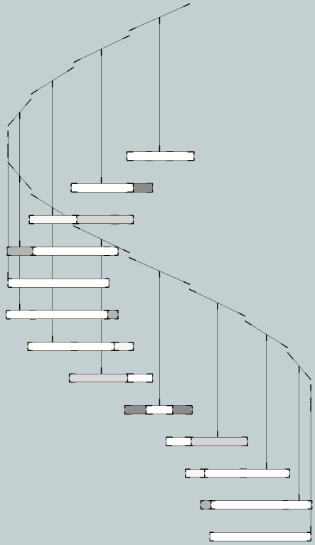
I wonder if someone could take a crack at getting my hand railings to line up. If it can be done, it should be possible to use the rail as a extrusion path which is automatically generated to match the stairs. You can see I'm close, but can't quite get it perfect.
-
Try starting the rail exactly above the tread's nosing an in pan extend the the next tread's nosing. As it is it's awkward to calculate...
-
I guess I wasn't clear - it is a Dynamic Component and the angles are calculated. It's not a construction problem, but a trig problem.
-
I know that...

But currently the start of the rail above each tread isn't vertically above the tread's nosing's outermost point - but it could be... I think you are making the calculation too convoluted. The rail's 'rise' is the height step-to-step. The tread's rail's start point could be the tread's nosing's outermost point... adjusted so its z=z+rail_height; the rail's top level is then the next tread's nosing point where again its z=z+rail_height OR the outermost tread 'plan distance raised by the 'rise'... ? -
Well, the reason I put the baluster in the middle of the tread is for symmtry. The DC is able to change the direction of the ascent - either up and to the right or up and to the left. I may be missing the obvious, but things seem to become even more complicated if I want to maintain this feature and the baluster is at the edge of the tread. In short, I think having the baluster in the middle actually simplifies things.

-
Ok, so if i forget about the baluster for now and make the aim just to dynamically create a spiral, that should simplify things a bit.
-
The 'sloping-handrail' and 'post' should be independent of each other.
It would be logical to place the post at the tread outer-edge center or near the front or back corner - the length is then calculated to suit the raking-rail above it, depending on where it is.
The sloping-handrail 'helix' should line up vertically above the outermost corner of the tread and the equivalent corner on the next tread up. The height of the rail is measured from the 'pitch-line'...
The 'going' of a stair-tread isn't the size of the tread itself as the treads should always overlap - it's actually the plan size of the tread - i.e. the tread less the 'nosing' overlap of the tread above it.
The 'rise' on each tread's raking handrail is equal to the rise at each step...
Your own helix tool should help with this math... -
Jim,
See SpiralStairCaseBuilder DC that I designed a while ago, it may help you:
http://forums.sketchucation.com/viewtopic.php?f=289&t=29484
I remember having a similar issue as the one you are having !!!
.........
In the end I decided to use handrailing guidelines in the DC.
The Spiral Staircase DC at the link above produces guidelines that are then used to construct the actual handrailing.
(a bit of manual finishing off).
That way you can use a bezier curve that gives a nice smooth finish to the handrailing.
(See Top Tips on Handrailing and the PDF at the link above).
..........
Hope this helps
Good luck with your DCRegards
Howard L' -
Jim,
I have been making my own DC Spiral Stair myself.
For the handrail, I have ignored much of the existing geometry and created the handrail guides independently based on a derived n-sided polygon.You cannot use trig calcs based on pure circles to get your railing length & angle as ultimately you are not making true arcs / circles, just a representation of such from a collection of vectors, hence your calcs will never be spot on (i.e. the curve is longer than the chord).
Be careful when calculating your unknown angle for the railing sections. You have used atan, but your unknown length is the adjacent, not the hypotenuse. Hence you should use asin.
Also watch out for the use of actuals for your calcs, rather than relying on your attribute settings as they can substantially different (e.g. in your model with the rise at 7" and the height at 98", your true rise is a little over 7.5").
I also noted that the component instances does not reset after repeated sizing using the height attribute. When going to attach the file I found it had grown to 8 mb. A quick purge from the model Info > Statistics dialog reined it back to 272 kb. Component count going from +300 to 18

HTH, Jon.
-
HI Jon,
Welcome and thank you for the help. Are you saying it is just not possible to accurately make a "Helix" DC?
-
Hi Jim,
I've been around for quite a while, but never felt I had much of anything to contribute. Time to try and give some back to all the great contributors on this forum.
I don't think the precision is there to get that last <0.1mm on the calculations.
I have ran the calcs through an excel sheet for both the spiral staircase and for some I did exploring making a dynamic reducer after looking at perryman's thread, but in each case the calcs are correct but lacking on Sketchup due to rounding errors.
I'm going to explore factoring of the calcs to reduce the rounding error, but I feel the final solutions will always come up minutely short.
In saying that, the incomplete geometry is only really visible when zoomed in, so for a lot of models it will not be a problem. For me though, this lack of complete accuracy is driving me mad for a solution.
Hello! It looks like you're interested in this conversation, but you don't have an account yet.
Getting fed up of having to scroll through the same posts each visit? When you register for an account, you'll always come back to exactly where you were before, and choose to be notified of new replies (either via email, or push notification). You'll also be able to save bookmarks and upvote posts to show your appreciation to other community members.
With your input, this post could be even better 💗
Register Login


Advertisement