Are SU's exported DXFs different somehow ?
-
Put even more simply... 2d DXFs make everything out of 'lines' including the segmented arcs/circles.
3d DXFs make 'real' CAD arcs/circles where segmentation is ignored... -
@tig said:
Put even more simply... 2d DXFs make everything out of 'lines' including the segmented arcs/circles.
3d DXFs make 'real' CAD arcs/circles where segmentation is ignored...thank you both and yes,understood. i may have misspoke when i said it was 2D. i was referring to the fact that the model exported was only in two axis (no Z). its what works best in tmcad to create tool path data. anyhow, it was exported as a 3d DXF, thus the scale was correct, etc.
below is an example. on the left is a 1/4" thick bracket. the middle and right side are what i export (thats what i meant by 2D)

this is a screen shot of what happens in tmcad. it dosent see the face and it thinks the hole is a solid. fwiw, it appears the same when imported into illustrator which is why i think the SU output is suspect.

-
I seldom export to 3D DWG from SU, but I tested by trying to create a similar part to yours, exported it and opened it in AutoCad 2011. To me the result was quite as expected: The edges became a circle and a loop of lines and arcs, and the face became a polyface mesh with a hole in the middle. No weirdness to be seen. So I am suspecting your CAD. Is the result the same even if you only have the edges to export? I am just wondering if your CAD is able to correctly interpret the 3D face geometry, or if the face geometry is partly covering the lines. Does your CAD have a 3D view where you could verify what is actually happening?
Just thoughts
Anssi
-
@anssi said:
<snip> No weirdness to be seen. So I am suspecting your CAD. Is the result the same even if you only have the edges to export? I am just wondering if your CAD is able to correctly interpret the 3D face geometry, or if the face geometry is partly covering the lines. Does your CAD have a 3D view where you could verify what is actually happening?
Just thoughts
Anssi
good thoughts Anssi.
good to know that autocad sees the model fine, maybe it is tmcad as you suggest.
yes i have done lines only and it seems happiest with that although its still not correct.
tmcad doesnt have a 3d viewer. it always shows the machine bed in a projection style format. once imported, your part shows as a single peice where you can then create multiples and edit as needed before outputting the tool path data.
i also stated talking to tmcad support in parrallel - well see what happens.
-
still limping along with this issue, but one interesting tid bit has come to light.
in working with the tech at torchmate, he has found that with the dxf created in su there is a tiny bit of text in the file way way off to the lower left. the key point is; i didnt draw it - su put it there
 BUT - i cant see it in su (or any other app) yet the apps know its there and its grouped or connected somehow which explains why any path type functions dont work; because its including this bit of text info as part of the model and i cant find it so i can delete it. the tm guru has tools the average human does not so he's able to see it - delete it - and do a connect path function and wala, all is well. i suspect if the text junk wasnt there in the first place you wouldnt need to do a fix like "connect path".
so what is this little bit of text junk and why is it being generated ?
-
I believe that SketchUp's Dxf translator is based on ODA's code. Fact is only Acad's dxf translator is correct. Most application translators are based on that application. The attached image is SketchUp's translation of a dxf file. The following image is an Acad viewers image of the same file. The SketchUp translation adds thickness to a ployline (the lower curve). The Acad viewer adds thickness, width, and bulge to the polyline.
-
Honoluludesktop,
What viewer are you using? I cannot duplicate what you see. I use AutoCad 2011. No thickness or width added to polylines or arcs. Face elements become polyface objects, while edges are correctly translated to corresponding ACAD entities. A cylinder has a circle both at the bottom and top.
Anssi
-
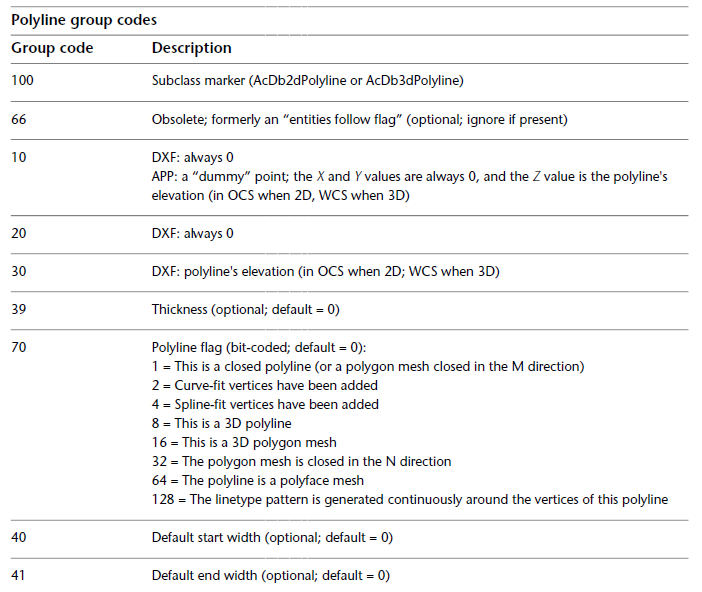
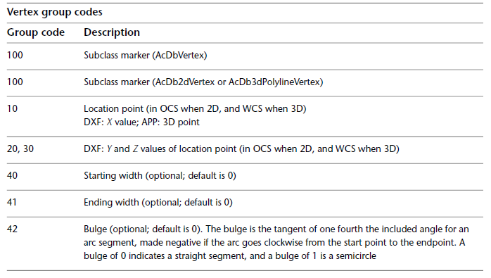
Autodesk Volo View. The subject DXF is a v2000 file. What was the source of your DXF that includes lines, arcs, and polylines with thickness, width, and bulge? Typically, polylines do not contain those characteristic. Attached is the Autodesk v2011 DXF reference excerpt for polyline, and vertex (as polylines include vertexes).
-
Honoluludesktop,
What I did was draw a freehand object in SU, pushpulled it, and exported to ACAD 2010 with the SUPro exporter. The 3D polylines exported do not have any width, bulge or thickness attached either to the polyline itself or the vertices (checked with the entsel and nentsel autolisp commands). Group code 39 is missing altogether - as it says, it's optional. I wonder if the exports for different ACAD versions differ, or if VoloView is adding fantasy of its own. VoloView is itself a rather old application-I would recommend the latest TrueView version: It's free, it works with the 2010 format, and it can convert DWG files to older and newer versions, down to version 10 or 12 DXF, I think.
Anssi
-
Acad drawing elements are unlike other Cad applications. In Acad, a line can be a simple 3d line, or rectangle with thickness, and extrusion direction (vector). A acad line with a thickness of 0.0 is a line, with a thickness of 1 inch, it is a rectangle with a height of 1 inch. You can not make a line with thickness in SketchUp. The SketchUp importer changes a line with thickness into a face. In SketchUp, when you model a set of connected edges in the x,y plane(say a polyline), then you loft the edges in the z direction, Sketchup will change the connected line into connected faces, and edges. SketchUp's DXF exporter will not translate this model into a polyline with thickness. The following is a portion of an ASCII DXF with some of my notes prefaced with #. A DXF listing always starts with a group code then followed by the data. This sequence is repeated throughout. Thickness, and bulge are as the tables above indicates. Some of the group codes are documented under "common group codes for entities".
.
.
0 #Acad group code precedes every piece of data
POLYLINE #data is entity Name
5 #Acad group code for handle
29 #handle
8 #Acad group code for layer name
T-2DPLINE-3 #layer name
62 #etc.
5 #etc.
66
1
10 #Acad group code for x
0.0 #x
20 #Acad group code for y
0.0 #y
30 #Acad group code for z
0.0 #z
39 #Acad group code for thickness
2.4332129974000671 #thickness
40
2.0
0
VERTEX #first vertex in polyline
5
34
8
T-2DPLINE-3
62
5
10
-1.3768750602197291
20
-3.437321703110606
30
0.0
0
VERTEX #second vertex in ployline
5
35
8
T-2DPLINE-3
62
5
10
-0.8415682007917144
20
3.2296819097655769
30
0.0
42 #Acad group code for bulge
-0.9902342116099923 #bulge data
0
.
.
I do not know what AutoCad drawing elements require entity thickness, width, and bulge. At one time Acad dimension line arrow heads used a lwpolyline with width, but I do not know if Acad 2011 continues to do so.My copy of Volo View is good up to Acad 2000. Thanks for the info on TrueView. Had it on my system at one time, but didn't like, and removed it.
Hello! It looks like you're interested in this conversation, but you don't have an account yet.
Getting fed up of having to scroll through the same posts each visit? When you register for an account, you'll always come back to exactly where you were before, and choose to be notified of new replies (either via email, or push notification). You'll also be able to save bookmarks and upvote posts to show your appreciation to other community members.
With your input, this post could be even better 💗
Register Login


Advertisement