CAD DRAWING EXPORT
-
Paul
Is this what you want ?
You select a component-instance/group and all of the 2d ortho's are auto-generated ?
It could be coded...
-
Yes, Yes!!!

-
Jim has already done the ortho views plugin. We just need the hidden lines.
-
@dave r said:
Jim has already done the ortho views plugin. We just need the hidden lines.
Exactly!
Although a 'flattened' version of all views in a 'collection' would export to CAD better... -
True, true. And you've already got a flattening plugin, right?
-
@dave r said:
True, true. And you've already got a flattening plugin, right?
The 'Project to Plane' type tools would be relatively easy to adapt [I hope...]
It's just arranging the pieces and working out what goes onto the 'hidden line layer'...
I'm just going to think about it over a pie and a pint in the pub down the hill...
-
The main thing is control over everything - so many variables
For example projection type- first angle / third angle
Hidden line details.
viewing details from behind that are hidden with dashed linesPerimeter profile
The outline of the item thicker or on a different layer , ( Much like outline mask )
I used this style a lot in Italy when working on AutocadIam sure there is more we could do with this
Thanks
Paul
-
@paulhankin said:
The main thing is control over everything - so many variables
For example projection type- first angle / third angle
Hidden line details.
viewing details from behind that are hidden with dashed linesPerimeter profile
The outline of the item thicker or on a different layer , ( Much like outline mask )
I used this style a lot in Italy when working on AutocadIam sure there is more we could do with this
Thanks
Paul
I'm thinking.........
I can [easily?] project the component's vertices onto the 6 ortho planes, in silhouette and also 'all'.
I have to think of ways to move the various edges to layers for CAD to use [including working out edges that are only partially hidden at say one end]...
You'd need t set up a CAD template that has pens mapped to thickness, where say 3D was white-continuous, 2D was red-continuous [thin], 2D-OUTL was yellow-continuous [heavy] and 2D-HIDN was grey-dashed [thin-dashed]. What CAD do you use? I could probably make you a ACAD template...
Be in touch later... off now... -
I use obviously Sketchup, Rhino 3d, Autocad for all detailing of parts
Must be able to Handle single groups, components , whole model
Have options maybe to select the parts you want to produce elevations / drgs and produces seperate files for each element in the model or selection.
There is so much you could do with this
also a weight added option based on the volume of the item x mass index ie for steel would be volume x 7.85
from this you could itemise each part say in the name of the component and it would produce a CSV file or excel sheet based
on group name / id , gross length of part say and weight. it then could be exported to autocad or simply print for estimating purposes.i think the profile plugin already recognises the part from the selection menu. maybe with permission the profile plugin could be utilised to save time re-writing the code for steel selection of parts etc.
Another element is developing intersections on tubes and the male female relationships of all cuts - thats for another time though i think!!
I think if this was developed right it could give other programs a run for their moneyPaul
-
just downloaded ortho views from smustard
in the plugins folder it goes
it doesnt do anthing when you press button on toolbar what is all this about
Just brought it and i cant use it
Paul
-
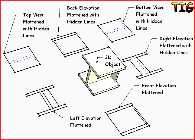
Make a group or component of the model or at least select the group or component for which you want the ortho view. Select it and then click on the button.
You'll wind up with something like this.

Wish I could have a pie and a pint.
-
Tried component / group everything and when i click on it nothing happens
Thanks
Paul
-
I like what TIG is suggesting, especially if it can be applied to interior elevations, and scenes. Architects requirement are unique when it comes to sections, and interior elevations. Would be nice to get input from engineers of different disciplines.
-
A simple solution might be to export two views: a wireframe view and a hidden-line view. Then you import the first into CAD, assign the dashed linetype of your choice to all the lines, and then import the hidden-line view and place it directly over the first one. If the excess lines worry you, you can use the "Overkill" feature in AutoCad (I think it is part of Express tools) to delete at least part of them.
Anssi
-
@anssi said:
A simple solution might be to export two views: a wireframe view and a hidden-line view. Then you import the first into CAD, assign the dashed linetype of your choice to all the lines, and then import the hidden-line view and place it directly over the first one. If the excess lines worry you, you can use the "Overkill" feature in AutoCad (I think it is part of Express tools) to delete at least part of them.
Anssi
Thats not the point, i have already been doing this up til now and when you have 100s of single parts it becomes very time consuming.
The idea of this discussion is to find an automated way of exporting these elements and improving work flow.
NOt being funny just want to hit the nail on the head so we can find a solution to this weekness of Sketchup when it comes to final detailing of drawings.
Thanks
Paul
-
I'm on to it...

-
-
Circle / radius problem solution?
Faceted circles / Radi - When exported convert all circles to a high segment polygon,via a input box
Ie a circle that has 10 edges could be converted to a circle with 100 edges giving the appearance of a more precise circle
depending on the tolerance of a hole. and insert a cross hair in the centre to denote the centre of the circle of a standardised size say 5x5mm or an input box could include this feature to choose.This then could have an option to convert all holes in model , voila problem sorted
obviously this would only work on flattened geometry for export to 2d cad cutting , say laser cutting
The segmented circles and radius could be put on a layer
the Centre mark could be put on another layerTurn off the circles layer etc..
You could then use the centre mark as ref to redraw circles in autocad if required rather than use 3 point circle ( less accurate on faceted circles )
More control!
What do you think?
Thanks
Paul
Hello! It looks like you're interested in this conversation, but you don't have an account yet.
Getting fed up of having to scroll through the same posts each visit? When you register for an account, you'll always come back to exactly where you were before, and choose to be notified of new replies (either via email, or push notification). You'll also be able to save bookmarks and upvote posts to show your appreciation to other community members.
With your input, this post could be even better 💗
Register Login


Advertisement