• Login
sketchucation logo sketchucation
  • Login
πŸ€‘ SketchPlus 1.3 | 44 Tools for $15 until June 20th Buy Now

[Plugin] Slicer v4.3 20110619

Scheduled Pinned Locked Moved Plugins
102 Posts 20 Posters 137.5k Views 20 Watching
Loading More Posts
  • Oldest to Newest
  • Newest to Oldest
  • Most Votes
Reply
  • Reply as topic
Log in to reply
This topic has been deleted. Only users with topic management privileges can see it.
  • E Offline
    eco_artbarn
    last edited by 14 Feb 2010, 22:59

    hey I have been looking for this for ages to help my pupils with our laser cutter but i have been trying to down load slicer 3.1rb but i cant work out where to put the text version.
    is there a slicer 3.1.rb file that i can just save and load into plugins folder?

    cheers

    1 Reply Last reply Reply Quote 0
    • T Offline
      TIG Moderator
      last edited by 14 Feb 2010, 23:19

      http://forums.sketchucation.com/viewtopic.php?p=16697#p16697
      Save the linked file as Slicer31.rb into the Plugins folder - done...
      If your browser insists on making it another file type you can always use Select All on the page and paste it into a new empty plain text file and rename it with a .rb suffix NOT .txt ...

      TIG

      1 Reply Last reply Reply Quote 0
      • M Offline
        mariocha
        last edited by 15 Feb 2010, 03:01

        In our work, we often deal with terrains modeled as surfaces, not volumes, often very irregular. Making a volume out of them is sometimes quite hard, even with Joint Push-Pull.
        Is there a "slicer" that can make slices from a surface ? Slices would then be only segments. πŸ˜„

        %(#008000)[Mario C.
        Every rule has exceptions, but some.]

        1 Reply Last reply Reply Quote 0
        • T Offline
          TIG Moderator
          last edited by 15 Feb 2010, 09:03

          To give a meshed surface a volume requires a bit of planning...
          You select all of the perimeter edges.
          Then use my tool ExtrudeEdgesByVector to extrude all of these edges vertically downwards (-ve Z / blue) far neyond the lowest one.
          Check that the faces are 'outwards'.
          Leave the extrusion in its group for now.
          Edit the group and draw a large flat rectangular plane facing down [reverse if necessay] located below the geometry, but so that it intersects with ALL of these new vertical faces.
          Select All inside the group and 'Intersect with Selected'.
          Erase the unwanted bits of the rectangle and change your view so you can easily 'select by fence' the bits of the vertical faces below it - delete them.
          Close the group-edit and select all of the mesh and Edit-Copy.
          Edit the group again and Edit>PasteInPlace
          Now you have a 3D volume with the top as a mesh...
          Move it to one side or copy the group and paste it into an empty model - and you can Volume or Slice, or whatever you need to do...

          If you have two meshes - e.g. existing and proposed land surfaces - you can do a 'cut and fill' volume etc by intersecting them together and making a groups of what's left - there's a tutorial on that somewhere...

          β˜€

          TIG

          1 Reply Last reply Reply Quote 0
          • E Offline
            eco_artbarn
            last edited by 15 Feb 2010, 15:36

            Thanks TIG that works a treat.
            i am sure i have seen a slicer tutorial before where it adds the slots half way up and half way down, is there a way of doing that with 3.1?

            i slice in the x and then sllice in the y and lay the sections out flat, but if there was a way of adding the midway slots that would be a huge advantage

            let me know cheers ash

            1 Reply Last reply Reply Quote 0
            • E Offline
              eco_artbarn
              last edited by 15 Feb 2010, 17:16

              cool, when's it gonna be ready to unleash on us?

              1 Reply Last reply Reply Quote 0
              • M Offline
                mariocha
                last edited by 18 Feb 2010, 04:03

                Tig, I have tried your method to give a volume to a mesh surface. Not bad. But not it, for us.
                Having to do all these extrusion just kills the gain. (btw I used the term terrain where I should have used cliff and hill sides.)
                What we need is to replace our manual process of generating slice from the meshes, group&number them, and offset to get rib (& face) for cnc.
                Or maybe just a rb to make numbered groups of our slice lines and then flattened copies ? πŸ˜„

                %(#008000)[Mario C.
                Every rule has exceptions, but some.]

                1 Reply Last reply Reply Quote 0
                • T Offline
                  TIG Moderator
                  last edited by 18 Feb 2010, 10:14

                  mariocha - I don't fully follow you...
                  To work out Volumes there are Volume Tools - Slicer is a different thing ?

                  TIG

                  1 Reply Last reply Reply Quote 0
                  • T Offline
                    TIG Moderator
                    last edited by 18 Feb 2010, 10:15

                    There is a paid script SliceModeller that I unwittingly helped develop !
                    That adds slots to the slices... Slicerv4 might do that too... πŸ˜‰

                    TIG

                    1 Reply Last reply Reply Quote 0
                    • M Offline
                      mariocha
                      last edited by 18 Feb 2010, 11:47

                      Sorry, I meant
                      Slicer only works on volumes, so you suggested to make volumes out of our meshes (with ExtrudeEdgesBy Vector).
                      We would like to automate mesh slicing to rib. πŸ˜„
                      (giving an offset value to make the face)


                      mesh-to-rib.png

                      %(#008000)[Mario C.
                      Every rule has exceptions, but some.]

                      1 Reply Last reply Reply Quote 0
                      • T Offline
                        TIG Moderator
                        last edited by 18 Feb 2010, 12:57

                        Wouldn't it be quicker to make the 'curtain' and then use JointPushPull on it to give it a Volume then Slice it ?
                        Or are you looking for a Slice at Nodes option ?
                        Can you give a before and after example, with steps so I can understand your issues better... πŸ˜•

                        TIG

                        1 Reply Last reply Reply Quote 0
                        • M Offline
                          mariocha
                          last edited by 18 Feb 2010, 14:01

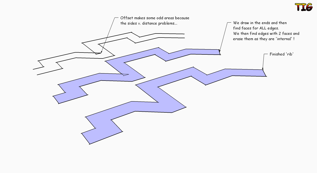
                          Indeed we tried with JPP. And we use it on simple meshes before Slicer. But often the mesh is too complicated, with acute angles, JPP results in a mess then. So an offset has to be done after the slicing.
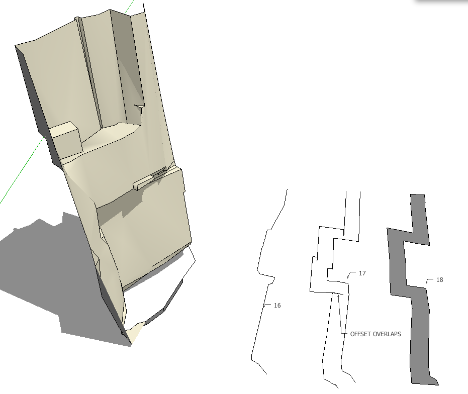
                          But I realise that the overlaps that Offset often do are going to be a problem that will need manual work anyway.
                          So we only need the part of the script that generates the slices, numbers and flattens them, like #16.


                          Example.png

                          %(#008000)[Mario C.
                          Every rule has exceptions, but some.]

                          1 Reply Last reply Reply Quote 0
                          • T Offline
                            TIG Moderator
                            last edited by 18 Feb 2010, 14:59

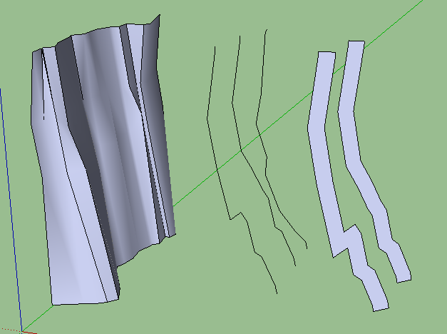
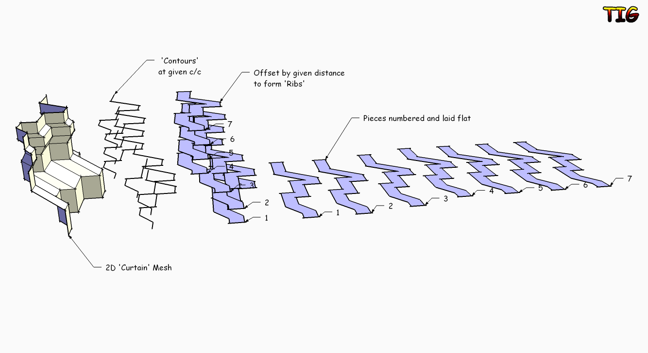
                            So if I understand correctly, you want a version of Slicer that can make slices through a '2D-mesh' - a 'curtain' of faces [that have no 3D values in plan - or the equivalent 'other' dimension] - and then represent these as group of lines forming 2D slices laid out on plan. I assume that you don't want any 'thickness' to these 'slices' as they are initially 'lines' anyway ?

                            Are these always in plan ?
                            If so there already is my ContourMaker ?

                            I see you seem to 'make faces' of the results - this could be added as an auto-offset by a desired distance of the lines closed into a face...

                            What is the exact use of these later on ? CNC work ?

                            Is this what you want ?sss.png

                            TIG

                            1 Reply Last reply Reply Quote 0
                            • M Offline
                              mariocha
                              last edited by 18 Feb 2010, 16:26

                              Yes Sir TIG, you got it right.
                              But these overlaps Offset creates (when some lines are shorter than the offset distance, I think) are going to be impossible to handle automatically, no?

                              %(#008000)[Mario C.
                              Every rule has exceptions, but some.]

                              1 Reply Last reply Reply Quote 0
                              • T Offline
                                TIG Moderator
                                last edited by 18 Feb 2010, 16:27

                                Watch this space...
                                Do you want to always cut in Z - it's easier that if I have to make XYZ versions ???

                                TIG

                                1 Reply Last reply Reply Quote 0
                                • T Offline
                                  TIG Moderator
                                  last edited by 18 Feb 2010, 16:37

                                  Like thisUntitled.png

                                  TIG

                                  1 Reply Last reply Reply Quote 0
                                  • T Offline
                                    TIG Moderator
                                    last edited by 18 Feb 2010, 16:41

                                    So the 'ribs' are vertical.
                                    How do you determine there rotation about the Z axis ?
                                    By axis X/Y or by Node angle bisector etc ?
                                    It is easy enough to make the closing edges 'horizontal'...
                                    πŸ€“

                                    TIG

                                    1 Reply Last reply Reply Quote 0
                                    • M Offline
                                      mariocha
                                      last edited by 18 Feb 2010, 16:43

                                      Great.
                                      My sections are always standing up. But at any angle on xy plane.
                                      Oh, and the top and bottom level have to stay the same if a face is created. Offset tends to change these if the initial top or bottom lines are slanted, as you know.

                                      %(#008000)[Mario C.
                                      Every rule has exceptions, but some.]

                                      1 Reply Last reply Reply Quote 0
                                      • T Offline
                                        TIG Moderator
                                        last edited by 18 Feb 2010, 18:36

                                        If you made a curve along the front edge then the ribs could be angled to match the angle-bisector to each pair of edges at a node, or square at the ends ?
                                        What would the typical 'scale' of this be - i.e. rib depth and rib spacing etc...
                                        Do these ribs project into the face, or out from it ?

                                        TIG

                                        1 Reply Last reply Reply Quote 0
                                        • M Offline
                                          mariocha
                                          last edited by 18 Feb 2010, 18:48

                                          A curve along the front edges ? Ha! on the floor, you mean? It would have to be a bezier, I guess.
                                          Ribs are a few inches (4") behind the faces.
                                          Typical heights are 5' to 20', rib with of 10"

                                          %(#008000)[Mario C.
                                          Every rule has exceptions, but some.]

                                          1 Reply Last reply Reply Quote 0
                                          • 1
                                          • 2
                                          • 3
                                          • 4
                                          • 5
                                          • 6
                                          • 2 / 6
                                          2 / 6
                                          • First post
                                            28/102
                                            Last post
                                          Buy SketchPlus
                                          Buy SUbD
                                          Buy WrapR
                                          Buy eBook
                                          Buy Modelur
                                          Buy Vertex Tools
                                          Buy SketchCuisine
                                          Buy FormFonts

                                          Advertisement