sketchucation logo sketchucation
    • Login
    1. Home
    2. MichelC
    ℹ️ Licensed Extensions | FredoBatch, ElevationProfile, FredoSketch, LayOps, MatSim and Pic2Shape will require license from Sept 1st More Info
    M
    Offline
    • Profile
    • Following 0
    • Followers 0
    • Topics 3
    • Posts 9
    • Groups 1

    MichelC

    @MichelC

    10
    Reputation
    1
    Profile views
    9
    Posts
    0
    Followers
    0
    Following
    Joined
    Last Online

    MichelC Unfollow Follow
    registered-users

    Latest posts made by MichelC

    • RE: How to fold a plane around a curved surface?

      @dave r said:

      TIG, does that not result in a projection on the surface? That would be different from wrapping the flat windows around the dodger, no?

      Tools on Surface could be good if you know where the lines need to go on the curved surface.

      Shape Bender should allow you to take the flattened dodger surface with the glazing and wrap it back up. I would probably only work with the part of the dodger that has the glazing and not include the bit that wraps over the top.

      On the other hand, I wonder if it wouldn't be easier to create a pleasing line by laying the glazing out on the curved surface. Seems it would be a bit like creating the proper sheer line. Much easier to get right on a 3D boat that on a flat drawing.

      Dave, I tried laying out the windows on the dodger front but i couldn't get curved (horizontal) lines on the dodger front because the dodger front is not a neat arc. It's a mix of two arcs and two straight lines nearing the aft end of the sides of the dodger. I still haven't figured out how to do this. I'm now trying to place the windows separately in front of the surface and then push/pull them through the dodger surface and then intersect. See what happens.

      Michel

      posted in Woodworking
      M
      MichelC
    • How to fold a plane around a curved surface?

      Hello all, although not strictly a woodworking issues, I post my question here because this subforum has a few experienced SU users. I ran into a problem with folding a plane containing a set of windows around the front of a dodger, for the non-sailors: a doghouse over the front end of a sailboat cockpit. See the picture and you know what I mean.

      In the background you see the flattened dodger that I used to draw the windows on. Drawing the windows right on the front of the dodger was no way to go, I couldn't get them to line up right. The windows are not rectangular, the vertical edges line up along perpendicular lines from the top to the bottom of the dodger front and the horizontal lines of the windows run along arcs parallel to the top edge of the dodger.

      I tried the sandbox tool and TIG's superdrape but the sandbox doesn't really fold around the surface, it projects the plane vertically (down) on the surface. Superdrape wouldn't work for reasons I don't understand, it keeps telling me that group1 has to be above group2. I moved around the window-group1 to all directions upward but Superdrape wouldn't budge. I also tried Shape Bender but I can't get the lines (straight and curved) right.

      Any way to get these windows down on the front of the dodger?


      Dodger3.jpg


      dodger3-1.jpg

      posted in Woodworking
      M
      MichelC
    • RE: How to get from 3D model to 2D construction plans?

      That's a sweet little swinging bunk!

      Michel

      posted in Woodworking
      M
      MichelC
    • RE: How to get from 3D model to 2D construction plans?

      Dave, another great tip, the joint push/pull plugin! Many thanks! I should have known this weeks earlier.

      Michel

      posted in Woodworking
      M
      MichelC
    • RE: How to get from 3D model to 2D construction plans?

      Dave, nice lake, from this distance it looks a bit like the lakes in Northern Italy, but with a larger marina.

      You made me aware of the benefit of using components in stead of groups, if I need to alter the model, the panels on the grid change with it. I hadn't seen that as a benefit, more as a disadvantage.

      Another problem I have is the fuselage sides. In the model they have texture, but zero thickness. In real life they will be 15 mm of 20 mm thick. The connection between decks and sides is not constructable in the way it is in the model now. In reality the sides need to be tapered down to receive the deck edge and the shape of the bulkheads changed perhaps but I don't see a way to model that without thickening up the sides. The sides are single curved, if you look from above, they have a shallow S-curve. I can't push/pull them to a thickness because of this curve. Do you see a way to thicken the sides to real life proportions?

      Michel

      posted in Woodworking
      M
      MichelC
    • RE: How to get from 3D model to 2D construction plans?

      Hi Dave,

      About not laying the parts flat but slap them vertically against a sheet.....good thought. I am still lacking in 3D thinking, that's clear, indeed there is no need to turn parts flat on the floor. Removing the thickness of the bulkheads and turning them into a simple line drawing was necessary to get the part as .dxf into Astra for nesting. So I have to find out if I can use the Grid plugin to make a vertical grid. I really need a scalable grid around the parts to be able to convert them to full size saw patterns.

      I'm amazed that at your location (Minnesota, right?) the ice was so weak. We've had ice here in the Netherlands for the third year in a row, after 8 years of mild winters without ice. A little ice age now, if you ask me. So I thought it's about time to finally invest in building an ice boat. I've sailed a borrowed DN for a day 30 years ago, and I still remember that day as if it were yesterday, an unforgettable experience!

      Here's another teaser for you to start on an iceboat too.

      Cheers!

      Michel


      Bluebird 0.83.jpg

      posted in Woodworking
      M
      MichelC
    • RE: How to get from 3D model to 2D construction plans?

      @dave r said:

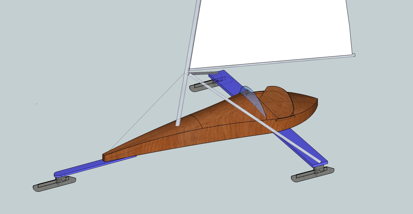
      Cool looking ice boat.

      I think a lot of the labor reduction will come in the way you make your components. You can use strategies such as setting the orientation of the component axes to aid in laying them out for patterns. As to flattening the skins, you can use any of several unfolding plugins (see the Plugins list--red button at the top) but keep in mind, the precision will be impacted by how many segments you've used to approximate the curves you draw.

      LayOut from the pro SketchUp package would be a big help for this so you might want to investigate that.

      How do you plan to layout and cut the skins? Are they thin plywood? Veneer? Is the boat cold molded? So many questions but a lot of what you need to do will be driven by what information is needed to create the parts.

      Hi Dave,

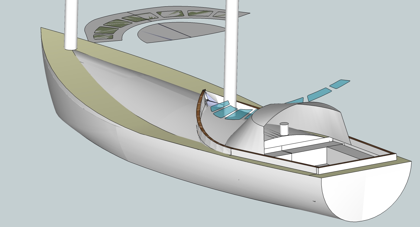
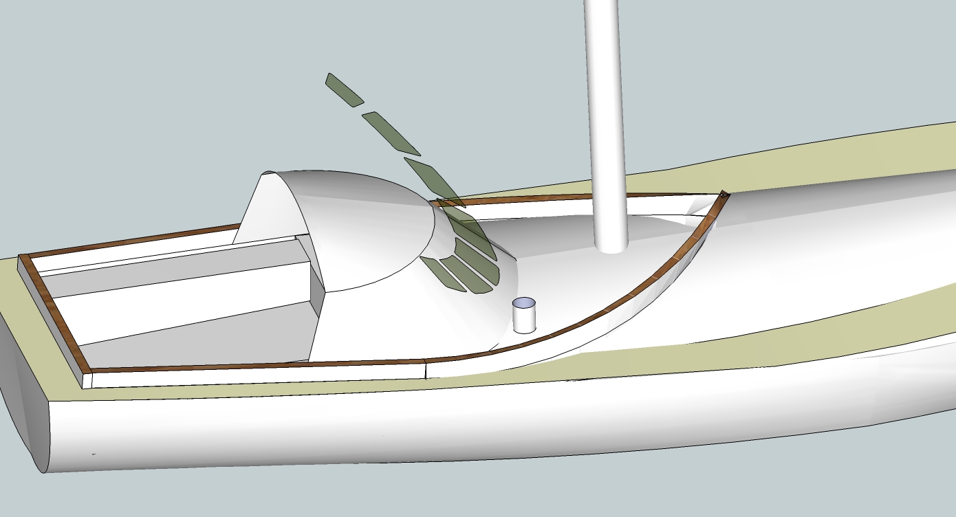
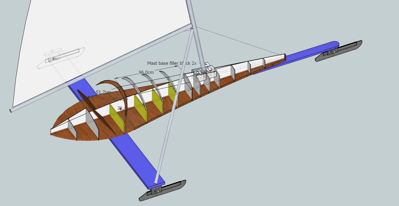
      The two-seater iceboat will be made from 5 mm plywood. And some doubled up reinforcements of 15 mm. The bottom is flat, sandwich of 2 x 5mm ply and 15 mm foam in between and some solid ply reinforcements. The sides are three layers of 5 mm ply scarfed together and laminated to the sides of the bottom and the fixed bulkheads. The yellow bulkheads in the pic are temporary, just there to assist in shaping and laminating the sides. If the boat is not stiff enough in way of the cockpit, an extra layer of 5 mm ply is laminated to the inside of the sides. Decks will be 5 mm ply. The mid deck will be removable so you can access the steering gear on the cockpit floor and when sailing without cover maybe have space to take a child between the knees when sailing.

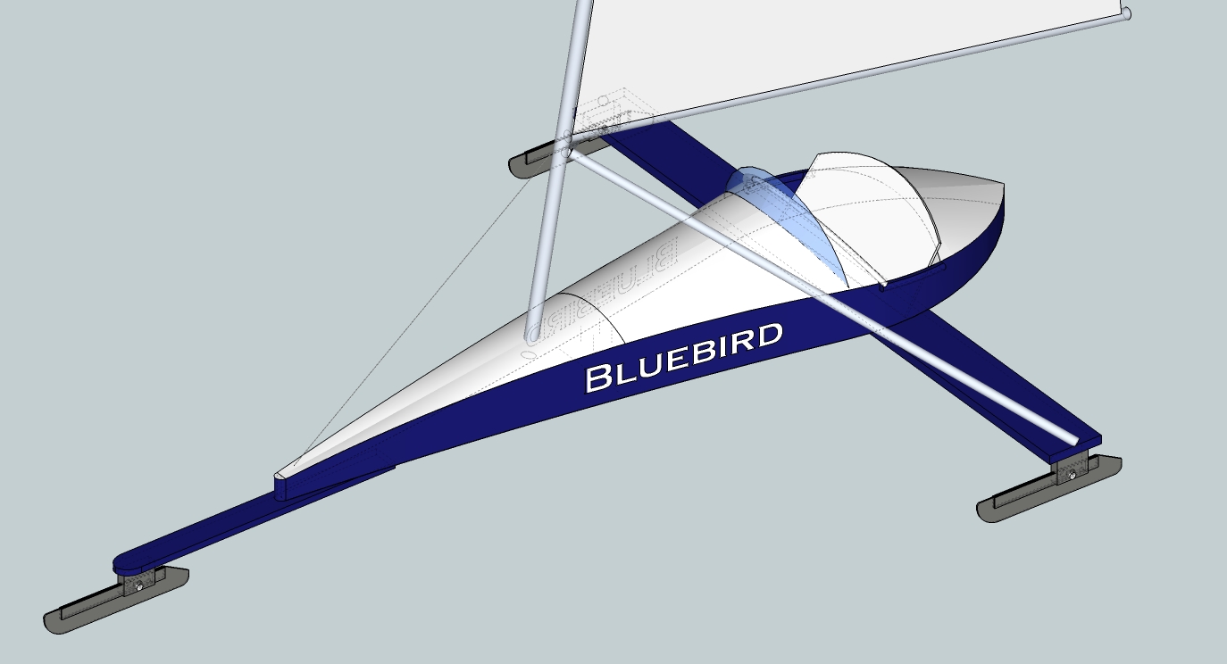
      For now this is a one-off project so the parts will be sawn by hand. I will probably be building two boats side-by-side and sell one to recover the costs. If it works out well, I perhaps offer the plans and building instructions or a kit for sale. This iceboat is designed to use standard DN iceboat hardware and a standard Laser dinghy rig supported in way of the boom by one stay and two struts.

      While making the model I spend lots of time calculating strengths, weights and dimensions to keep the total weight low while having a strong enough structure. Total weight of the fuselage (including epoxy resin and glass sheathing, ex hardware) is now a little over 45 kgs. Heavy, compared to a DN iceboat (21 kgs). But my design is a two-seater tourer, not a racer. But perhaps I'm still over-dimensioning. For stability and sailing weight distribution calculations I used the Center of Gravity (CoG) plugin. First separate CoG's for the wood parts, the rig and the crew, next a combined CoG based on the three.

      In SU, I flattened the skins with the 'Unfold tool' plugin, after first creating the skins with Fredo6's Curviloft. Cool plugin that is! Unfolding was lots of work with so many small triangles making up the decks. To check accuracy of the unfold action, I measured the tops of the bulkheads to see if the flattened deck skins were wide enough. They were.

      I first made the mistake to make components of the bulkheads, then copy them and rotate them flat. Next I removed the top surface and lines (bulkheads were 5 mm and 10 mm thick) to create a flat pattern....et voila.... the original component was taken apart too! I learned when to use components and when groups!

      I started the model by integrating two 'coffins' - rectangular boxes -, one with the horizontal curves and one with the vertical curves and then erasing all lines and planes outside the desired shape. Was like cutting through a block of styrofoam with a hot wire. Then I created the bulkheads with the curved tops and layed skin on these to form the decks.

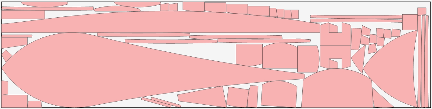
      I used the demo version of Astra true shape nesting to nest all the parts on plywood sheets. Below is a pic of an automatic nesting operation done by Astra. It's a double length sheet first scarfed together. In the demo version of Astra you can't export .dxf files for laser cutting, but you use the pic (a screenshot) to get an idea of an optimal nesting. I use the Grid plugin to lay out all the parts on a 5 cm x 5 cm grid in SU. Then I will print this on A4 paper and with the grid as guidance, draw the parts on flipover sheets with a true grid of 5 cm x 5 cm. Symmetrical parts have to be drawn only in half parts.

      And to all other respondent: thanks for your assistance, I'm going to look into every tip.

      Mike.


      ScreenShot001.jpg

      posted in Woodworking
      M
      MichelC
    • How to get from 3D model to 2D construction plans?

      Hi all,

      I'm an amateur with some experience in yacht design and construction. I'm using SketchUp 8 free for a couple of weeks now and I'm amazed by what it can do and how relatively easy it is to learn to use, compared to other CAD software. I've designed a two seater ice yacht (see picture), including the internal bulkhead structure which is shown in the next picture.

      I'm now in the process of converting the 3D model to 2D plans for construction. I found and use several plugins to help with that; I need to flatten curved surfaces, remove bulkheads one by one from the 3D model and lay them all flat on a grid as reference to make full scale plans on paper later on. Nesting all the parts efficiently on plywood sheets is also a lot of work, even with a demo version of a professional nesting program I found (Astra true shape nesting).

      I find this conversion from 3D model to 2D construction plan very labor intensive and I wonder if there is an easier way to do this. For a professional (which I'm not) this process may perhaps be known and a piece of cake.

      All tips on how to do this and pointers to additional plugins to help are welcomed.

      Mike


      IJsvogel 0.83.jpg


      IJsvogel 0832.jpg

      posted in Woodworking
      M
      MichelC
    • How to get from 3D model to 2D construction plans?

      Hi all,

      I'm an amateur with some experience in yacht design and construction. I'm using SketchUp 8 free for a couple of weeks now and I'm amazed by what it can do and how relatively easy it is to learn to use, compared to other CAD software. I've designed a two seater ice yacht (see picture), including the internal bulkhead structure which is shown in the next picture.

      I'm now in the process of converting the 3D model to 2D plans for construction. I found and use several plugins to help with that; I need to flatten curved surfaces, remove bulkheads one by one from the 3D model and lay them all flat on a grid as reference to make full scale plans on paper later on. Nesting all the parts efficiently on plywood sheets is also a lot of work, even with a demo version of a professional nesting program I found (Astra true shape nesting).

      I find this conversion from 3D model to 2D construction plan very labor intensive and I wonder if there is an easier way to do this. For a professional (which I'm not) this process may perhaps be known and a piece of cake.

      All tips on how to do this and pointers to additional plugins to help are welcomed.

      Mike


      IJsvogel - Kingfisher in English


      Bulkheads

      posted in Newbie Forum sketchup
      M
      MichelC