Hi,
Thought I would report back. I managed to get it all sorted, thank you very much for the tips!
It's on it's way to being printed!
Bas
Hi,
Thought I would report back. I managed to get it all sorted, thank you very much for the tips!
It's on it's way to being printed!
Bas
Tx all, the email notification did not seem to work. So I thought there was not replies. Instead there is these very detailed, very helpful ones!
I was modeling at the real size, that way it was easier to measure something and then enter the exact dimensions. But being metric, drawing everything in meters and then later sizing it down will be easy.
Will have to read thru the replies in detail. Lots that doesn't mean much to me yet.
Effort gone into these replies is MUCH appreciated!
Hello,
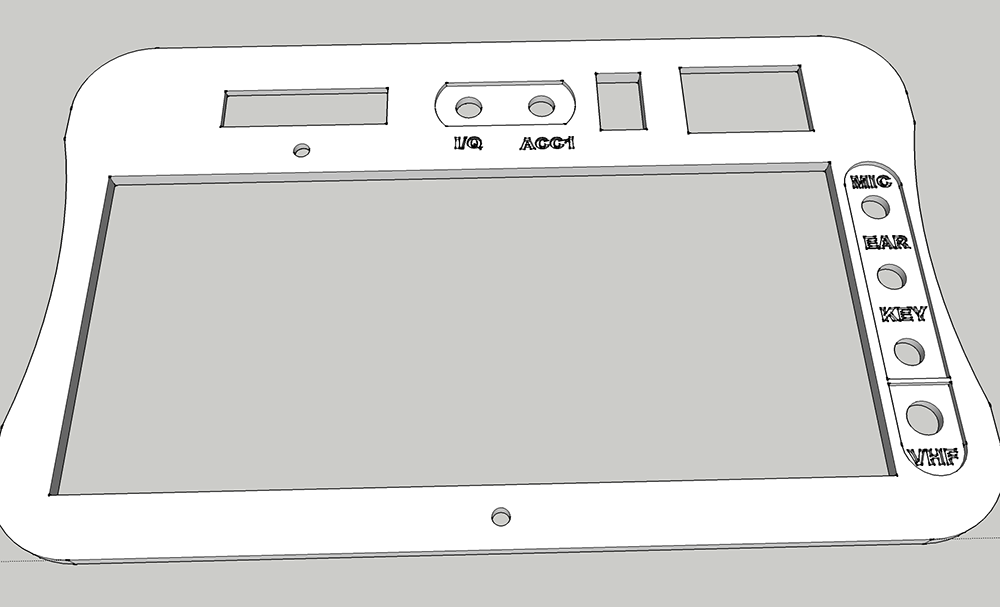
I'm trying to model a panel that will be used with a radio. I hope to 3D print this.
Panel has two features that are no simple thru-holes.
A space where a battery meter will sit. The LCD is 2mm thick, the panel will be 4 mm. I recessed the cutout for the PCB from the back. In Sketch-up it looks OK, but when exported to STL and loaded by a 3D printer website, it does now show the hole for the LCD (the full thru-hole)
A space where several audio and coax bulkhead connector go thru. Since the bulkhead connectors only span about 2.5mm I wanted to make a somewhat nicer looking rounded inset from the top.
No matter what I try, I can't get that to work. Every time I try to Push/Pull that face, it moved that plane. I can get it to fill the face back in, but then I can't get the round cut-out to select. I've used guides to find the middle of the hole, made a new circle overtop of the exact same size, but that still does not allow me to select the face inside the circle.
Getting somewhat frustrated after trying this for a few hrs 
Any hints and tips welcome!!
Bas
P.s Also attached the flat file I start from. The outer borders are for me to show the visual size of the items going in. Inner borders are the actual cut-outs