[Plugin] Slicer v4.3 20110619
-
Error; #<TypeError; reference to deleted Face>
C;/PROGRA~2/Google/GOOGLE~1/Plugins/Slicer31.rb;454;in `pushpull'
C;/PROGRA~2/Google/GOOGLE~1/Plugins/Slicer31.rb;454;in `calculate'
C;/PROGRA~2/Google/GOOGLE~1/Plugins/Slicer31.rb;453;in `each'
C;/PROGRA~2/Google/GOOGLE~1/Plugins/Slicer31.rb;453;in `calculate'
C;/PROGRA~2/Google/GOOGLE~1/Plugins/Slicer31.rb;363;in `each'
C;/PROGRA~2/Google/GOOGLE~1/Plugins/Slicer31.rb;363;in `calculate'
C;/PROGRA~2/Google/GOOGLE~1/Plugins/Slicer31.rb;804
C;/PROGRA~2/Google/GOOGLE~1/Plugins/Slicer31.rb;454;in `call'
C;/PROGRA~2/Google/GOOGLE~1/Plugins/Slicer31.rb;454
this was the response
no geom on hidden layers
-
OK... sounds like the resulting slices are failing to pushpull because a face isn't 'enduring'...
It's easy enough to trap for that BUT it begs the question - what is the actual problem?Can you post/PM a zipped version of the surface/volume you want to slice, with some notes about what you want to achieve... and I'll look at it... and report back...
-
Here's a new version http://forums.sketchucation.com/viewtopic.php?p=16689#p16689
Please read the notes - particularly about removing earlier version[s]...
It should now make all slices, even if your 3d form is non-solid and so complex that a meaningful slice cannot be made/faced/extruded; it will no longer stall even if some slices are not made as you might hope... To ensure good results ensure that the form you are slicing is 'solid' or at least simple enough the slice if it's not...
[Sir's recent problem was from an overly complex form... BUT this update does mean that even that doesn't stall part way through the slicing...] -
thanks for updating this fantastic plugin, will give it a whirl now!
-
Here's an updated version
http://forums.sketchucation.com/viewtopic.php?p=16689#p16689An Image export option has been added.
Usage:
Run the main Slicer tool and make your flatten slices set.
Then preselect the 'Flat-Slice-nnnnnnnn' group and type into Ruby Console:Slicer::images
It then makes .png image files of 0.9 quality, with no anti-aliasing, each named after the slice; all within a folder with the model, named 'ModelName-Slice-Images-nnnnnnnn'. All images are made the same size [based on the screen] with the relative size of each slice maintained in the 'pixel sizes', so subsequent auto-cropping of the white-space leaves images that are all 'relatively sized'...
Tip: use a Style with a white '[back]ground', no profiles, no extensions, no endpoints etc so the images are as sharp as possible.

-
Despite studying and testing essentially everything in this thread, I'm unable to accomplish what I need.
I'm laying out laminated flooring in my home. Each laminate plank measures ~ 4"x30"x3/8". I've made a group of the plank.
I need to "saw" the planks to varying lengths, and save the pieces sawed off, minus 1/8" saw kerf. The saved pieces will be used where short pieces are needed on the opposite end of the room.
I'm prepared to give myself a dope slap if I've failed to recognize the solution in this thread.
SU8 Pro, Win7
Gary
-
Gschwartz9
I think that Slicer really isn't the tool you want...
You are using groups rather than components which will make editing just one easier...
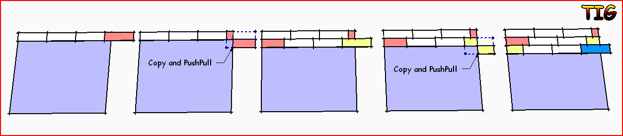
You simply lay out the first line of planks as you would in real life.
Using Move+Ctrl then Nx to make enough copies off to the right.
The last one will need to be 'cut'.
Copy the last group to the side of itself [Move+Ctrl with snap-points as appropriate].
Now edit that copy and pushpull the end of the copied plank that's inside the room until it is level with the wall/skirting face [or door=threshold etc as appropriate to its location], now you could pushpull it another 1/8" to account for the saw cut [but this level of accuracy is probably unnecessary - I suspect you won't have modeled the rooms skirting trims and left a 1/2" movement gap around the perimeter etc...].
You can also repeat on the last piece in the first line, editing it so the cut of end is no longer there...
Take the 'off-cut' and place it at the left-hand start again, next to the initial piece.
Now place a whole plank to the right of that and repeat the Move+Ctrl then Nx to make enough copies off to the right.
Again the last one will need to be 'cut'.
Repeat the copying it and pushpull the end of the copied plank that's inside the room etc as before.
Keep repeating this until all of the floor is covered.Note that if you want to have regularly spaced butt-joints, rather than whatever the off-cut gives you [e.g. the planks are 'tile-like' rather than 'wooden-planks'] then you need to mark the tiling repeat as a line in the initial group and slide the off-cut at the restart until it aligns with the mark - if it can't then it's has to be discarded and you use a new plank - if you are trying to stagger the plank ends in alternate rows slide the next start plank to align with a mark - leave the part you'd actually need to cut off sticking into the wall for now... make the run of planks until the last one that needs cutting to fit - if it'd be smaller than the off-cut you would have from the first plank in the lien then you can make the copy of the plank and edit/pushpull that plank and its copy in opposite directions so you have the two pieces... then take the piece current stuck in the wall [I recommend you do this using a 2d copy of the floor plane without the walls to get in your way, or use layers to hide most stuff]... and use that at the right-hand end, again cutting it as needed to fit [this time the final off-cut will be useless because it'll not have a start or end slot to connect to another plank!]...
It's easier to do it than write it...
-
Thanks TIG for the clever workaround. This will get me thru my current project.
Your procedure is easy to follow and gets the job done. I have a couple of issues with the routine that may be unreasonable expectations. One: I've applied textures to the sides and ends to discern between tongue & groove ends & sides. When I shorten via PP, the texture remains, telling me it's a tongue or a groove when it's actually neither. Second: Compared to AutoCad's Slice command, it's more time consuming. With the ACAD Slice command, a plane is defined by two intersecting lines. Any object intersected by this plane can be sliced, with the option of retaining either or both resulting pieces. This capability is what I'm looking for.
This has value in construction, carpentry & plumbing where materials are purchased in finite lengths that need to be cut to fit, and the remainder retained for use.
You indicated that I may be looking in the wrong place. Can you point me in the right direction?
Gary
-
Gschwartz9, you say you have SU8 Pro. Have you tried the "Solid Tools", specifically the "Split" feature?
-
You are seriously over complicating the issue by adding a texture to the planks.
Why not go the whole hog and add the fully modeled t&g edges all round [and then have the difficulty of snapping the pieces together]
Never forget that what you model is exactly that - 'a model' it does not need to represent really exactly - in the case of these planks the face size is what's important to you, nothing else. I used PushPull in my example simply because I though it was the simplest to do - as Scaling would distort etc...
If you insist on using this 'textured way' then have you looked at say the 'Zorro2' tool which will cut up solids, or as already suggested the 'Solid' tool ?
A simpler way might be that IF you have to know which edges are t&g etc then you can add a small 'marker' shaped like a T to the top-left corner of the original plank group and an equivalent G 'marker' to the bottom-right corner.
The two edges next to a T are always 'Tongued' and the two next to the G are always 'Grooved'. When you split a plank [using Zorro/Solid tools etc, NOT PP] you can then tell which end is which type for reusing later. If a plank's off-cut has neither marker then it an unusable central bit and needs to be discarded.
As you should always lay the floor from the top-left corner of the room, adding planks to the right until you reach a wall etc, and when that line is done you must start again at the left=most end of the laid floor, you should never need to 'rotate' or 'flip' anything [unlike real life!]... so the plank's 'up' long edge is always a 'tongue' and the plank's 'down' long edge is always a 'groove' anyway... -
Hey Tig! Now you van see what your hard work can do!!
http://www.qupix.nl/PROJECTS/STANDS/ROCKWOOL%20Utrecht%20Bouwb/PROJECTS_ROCKWOOL%20BOUWB.html
Greets!
Pep -
I agree that I'm overcomplicating this issue. I'll simplify my need.
Assume that I have an 8' 2x4 that will be sawed into a 5' piece and a 16" piece. I want to use the remainder elsewhere in my project. Assume also that for good reasons, the PP solution won't work.
I've tried: Subtract, Split, Trim, Zorro & Zorro2. All either don't do the job, or require significant "repair" work on the cut pieces. For example: Subtract initially appears to do exactly what I need by removing a narrow section of the 2x4 at the desired location. But, the 8' 2x4 component (or group) continues to be a single entity that requires exploding, then making components or groups of all the pieces.
I must be doing something wrong, but I haven't identified it in the tutorials. Also, it's hard to believe that a program as sophisticated as SU lacks such a basic tool that has broad application.
What am I missing?
-
Draw a line using the line/pencil tool at the point you wish to cut, select the offcut and group it and move it to your offcut pile.
Or better still, create a vertical plane at your cutting point, use this to intersect with the planks and separate the pieces.
Perhaps I'm seeing it too simply, ignore me if so.
-
I tried both methods, but unable to make either work.
Someone please tell me if my expectations are unreasonable, or point me toward a solution.
-
I still think Zorro[2] should do what you want...
I have 'chop.rb' [unreleased] that does something similar - simply splitting all of geometry inside the preselected things along the plane defined by 3 picked points...
I'll see if I can get it decent for the public... If I recall it only chops to one level of nesting - probably more than enough for you... but not great as a general tool...
-
@gschwartz9 said:
...
I've tried: Subtract, Split, Trim, Zorro & Zorro2. All either don't do the job, or require significant "repair" work on the cut pieces.This snippet of code can take care of the repair work, after using the solid tools (Trim?). Right click the group and select "Divide Group after Trim". Just be sure no loose geometry is touching it(groups & components are ok), otherwise they may be incorporated into the new groups.
divide group after trim.rb -
I'll give Zorro[2] another try. Also interested in your chop tool. You're right about only one level of nesting needed.
I think it would be great as a general tool. Examples: *Plumber working with sections of 2" copper pipe for a long run that has many changes in direction and varying lengths of pipe, *Landscaper laying tiles along a curved path, *Carpenter determining which length of lumber will be most efficient for a project that needs several pieces of varying lengths, *A craftsman determining how much of a very expensive wood he needs, *A retired Mechanical Engineer attempting to optimize usage of laminate flooring.
Of all the tools I've looked at, Section Plane seems to have the essence of what's needed. It lacks is the option for retaining both sides of the section cut. An enhancement would be user-selected distance between the sides. That distance would vary depending on the material being cut; e.g. copper pipe, construction wood, model-makers wood, concrete ...
Is the code for Section Plane available?
-
@kyyu said:
@gschwartz9 said:
...
I've tried: Subtract, Split, Trim, Zorro & Zorro2. All either don't do the job, or require significant "repair" work on the cut pieces.This snippet of code can take care of the repair work, after using the solid tools (Trim?). Right click the group and select "Divide Group after Trim". Just be sure no loose geometry is touching it(groups & components are ok), otherwise they may be incorporated into the new groups.
[attachment=0:1q6mm088]<!-- ia0 -->divide group after trim.rb<!-- ia0 -->[/attachment:1q6mm088]WOW!
This does the job. Thank you kyyu. -
One remaining question:
When I apply short reference lines to the edge of planks to use when I stagger the rows by 1/3 plank-length, the group is recognized as a group, but not a solid.
If I edit the group & erase the reference lines, it is recognized as a solid.
Where did I go wrong?
-
A solid is a group/definition where all edges have two faces - no more no fewer!
So faceless-edges, faces without a neighbor [a flap], internal partitions where an edge has three or more faces or otherwise 'solid' forms that meet on a common edge so that edge actually has four faces... will all report as non-solids...So to avoid 'unsolidness' ensure that all edges have two, and only two faces... and use other means of adding 'guides'...
Hello! It looks like you're interested in this conversation, but you don't have an account yet.
Getting fed up of having to scroll through the same posts each visit? When you register for an account, you'll always come back to exactly where you were before, and choose to be notified of new replies (either via email, or push notification). You'll also be able to save bookmarks and upvote posts to show your appreciation to other community members.
With your input, this post could be even better 💗
Register Login


Advertisement