[Plugin] Slicer v4.3 20110619
-
You are seriously over complicating the issue by adding a texture to the planks.
Why not go the whole hog and add the fully modeled t&g edges all round [and then have the difficulty of snapping the pieces together]
Never forget that what you model is exactly that - 'a model' it does not need to represent really exactly - in the case of these planks the face size is what's important to you, nothing else. I used PushPull in my example simply because I though it was the simplest to do - as Scaling would distort etc...
If you insist on using this 'textured way' then have you looked at say the 'Zorro2' tool which will cut up solids, or as already suggested the 'Solid' tool ?
A simpler way might be that IF you have to know which edges are t&g etc then you can add a small 'marker' shaped like a T to the top-left corner of the original plank group and an equivalent G 'marker' to the bottom-right corner.
The two edges next to a T are always 'Tongued' and the two next to the G are always 'Grooved'. When you split a plank [using Zorro/Solid tools etc, NOT PP] you can then tell which end is which type for reusing later. If a plank's off-cut has neither marker then it an unusable central bit and needs to be discarded.
As you should always lay the floor from the top-left corner of the room, adding planks to the right until you reach a wall etc, and when that line is done you must start again at the left=most end of the laid floor, you should never need to 'rotate' or 'flip' anything [unlike real life!]... so the plank's 'up' long edge is always a 'tongue' and the plank's 'down' long edge is always a 'groove' anyway... -
Hey Tig! Now you van see what your hard work can do!!
http://www.qupix.nl/PROJECTS/STANDS/ROCKWOOL%20Utrecht%20Bouwb/PROJECTS_ROCKWOOL%20BOUWB.html
Greets!
Pep -
I agree that I'm overcomplicating this issue. I'll simplify my need.
Assume that I have an 8' 2x4 that will be sawed into a 5' piece and a 16" piece. I want to use the remainder elsewhere in my project. Assume also that for good reasons, the PP solution won't work.
I've tried: Subtract, Split, Trim, Zorro & Zorro2. All either don't do the job, or require significant "repair" work on the cut pieces. For example: Subtract initially appears to do exactly what I need by removing a narrow section of the 2x4 at the desired location. But, the 8' 2x4 component (or group) continues to be a single entity that requires exploding, then making components or groups of all the pieces.
I must be doing something wrong, but I haven't identified it in the tutorials. Also, it's hard to believe that a program as sophisticated as SU lacks such a basic tool that has broad application.
What am I missing?
-
Draw a line using the line/pencil tool at the point you wish to cut, select the offcut and group it and move it to your offcut pile.
Or better still, create a vertical plane at your cutting point, use this to intersect with the planks and separate the pieces.
Perhaps I'm seeing it too simply, ignore me if so.
-
I tried both methods, but unable to make either work.
Someone please tell me if my expectations are unreasonable, or point me toward a solution.
-
I still think Zorro[2] should do what you want...
I have 'chop.rb' [unreleased] that does something similar - simply splitting all of geometry inside the preselected things along the plane defined by 3 picked points...
I'll see if I can get it decent for the public... If I recall it only chops to one level of nesting - probably more than enough for you... but not great as a general tool...
-
@gschwartz9 said:
...
I've tried: Subtract, Split, Trim, Zorro & Zorro2. All either don't do the job, or require significant "repair" work on the cut pieces.This snippet of code can take care of the repair work, after using the solid tools (Trim?). Right click the group and select "Divide Group after Trim". Just be sure no loose geometry is touching it(groups & components are ok), otherwise they may be incorporated into the new groups.
divide group after trim.rb -
I'll give Zorro[2] another try. Also interested in your chop tool. You're right about only one level of nesting needed.
I think it would be great as a general tool. Examples: *Plumber working with sections of 2" copper pipe for a long run that has many changes in direction and varying lengths of pipe, *Landscaper laying tiles along a curved path, *Carpenter determining which length of lumber will be most efficient for a project that needs several pieces of varying lengths, *A craftsman determining how much of a very expensive wood he needs, *A retired Mechanical Engineer attempting to optimize usage of laminate flooring.
Of all the tools I've looked at, Section Plane seems to have the essence of what's needed. It lacks is the option for retaining both sides of the section cut. An enhancement would be user-selected distance between the sides. That distance would vary depending on the material being cut; e.g. copper pipe, construction wood, model-makers wood, concrete ...
Is the code for Section Plane available?
-
@kyyu said:
@gschwartz9 said:
...
I've tried: Subtract, Split, Trim, Zorro & Zorro2. All either don't do the job, or require significant "repair" work on the cut pieces.This snippet of code can take care of the repair work, after using the solid tools (Trim?). Right click the group and select "Divide Group after Trim". Just be sure no loose geometry is touching it(groups & components are ok), otherwise they may be incorporated into the new groups.
[attachment=0:1q6mm088]<!-- ia0 -->divide group after trim.rb<!-- ia0 -->[/attachment:1q6mm088]WOW!
This does the job. Thank you kyyu. -
One remaining question:
When I apply short reference lines to the edge of planks to use when I stagger the rows by 1/3 plank-length, the group is recognized as a group, but not a solid.
If I edit the group & erase the reference lines, it is recognized as a solid.
Where did I go wrong?
-
A solid is a group/definition where all edges have two faces - no more no fewer!
So faceless-edges, faces without a neighbor [a flap], internal partitions where an edge has three or more faces or otherwise 'solid' forms that meet on a common edge so that edge actually has four faces... will all report as non-solids...So to avoid 'unsolidness' ensure that all edges have two, and only two faces... and use other means of adding 'guides'...
-
You could use "guide point/lines" placed by the "Tape Measure Tool". Or there are plugins that make center points (aka construction points) and you can copy/paste them after they are replaced. Or plugins that may place the construction point directly. The picture below, illustrates the two methods.
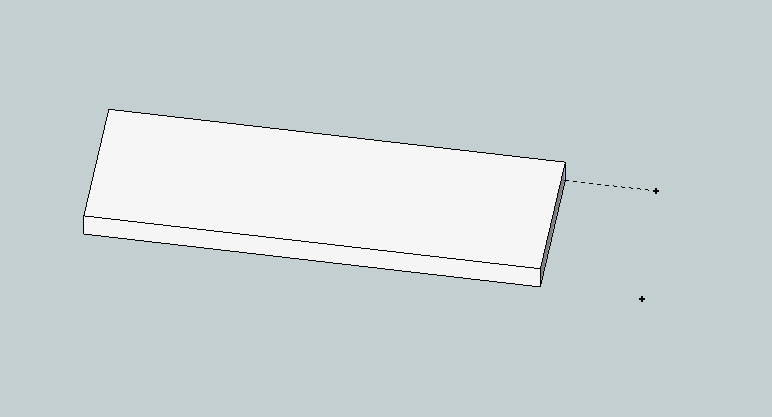
Or making construction lines, outside of the group, may turn out to be a better solution. That's how I normally do alot of my alignment. -
Is it possible to have variable spacing of the slices.
Such as the first slice is at the face of the object, second slice at 3", next slice at 8" and so on.Thanks,
Larry
-
Not unless you rewrite the code!
It would be possible if you rewrite the loop that steps through the slice spacing - instead of using the spacing to move the intersecting 'disk' in even steps, you'd compile an array of the spacings and then iterate those in turn...
Why do you want to do this ?? -
Tig,
I want to use something like slicer to locate bulkheads at exact locations along the fuselages of some aircraft designs that I am working on. I like the way it can take the slices and lay them out flat so that I can export them to my laser cutter.
Maybe there is a better way, I don't know.Larry
-
Make a large vertical rectangular face that will readily include the whole fuselage.
Group it.
Copy that group along the fuselage at the desired centers, typing in the exact dims as you go [Move+Ctrl...].
Double-click each face-group in turn and 'select-all' [double-click on the face].
Right-click and context-menu = Intersect > with Model...
The fuselage outline is imprinted on the face.
Erase any edges/faces you don't want.
Pushpull the required face[s] by the desired distance [tip once you've done a Pushpull you only need to double-click on a face to repeat the same 'extrusion']
Repeat this for all of the 'cross-sections' until you have all of the 'bulkheads' made.
To lay them 'flat' view in side elevation [perspective off] and use the Rotate tool on each one individually to flip them so they are horizontal.
When they are all done move them around in a plan view as desired... print off... -
Thanks TIG.
Attached is a quick and dirty sample of what I think you were talking about.Larry
-
That's about it... but I trust your fuselages are a little more complex!

Use layers to hide the fuselage [which I hope is grouped/componented] when you no longer need to see it...
Tip: when you are editing a group/instance you can switch everything else off during an edit - under the menu 'View' - 'Component' Edit - 'Hide Rest of Model' - that makes seeing what you are doing much easier! The fact it's hidden in the edit won't affect the intersecting you might do...
-
@tig said:
@xrok1 said:
@unknownuser said:
I have a [privately written and hopefully paid for] 'Slicer v4' that has such lines added etc for CNC work - watch this space.
hey, are you finally going to make your own and bust that slicemodeler @&&hole
I have written a paid commercial version [private] - Slicer_v4 - for someone for CNC use etc... it [or some of its ideas] might leak out to you too...
Did u ever decide to do this?

-
Yes and no...
I have two slicer-like commercial projects on... one day when they finish I hope to up date using some of the ideas in them... but don't hold your breath waiting...
Hello! It looks like you're interested in this conversation, but you don't have an account yet.
Getting fed up of having to scroll through the same posts each visit? When you register for an account, you'll always come back to exactly where you were before, and choose to be notified of new replies (either via email, or push notification). You'll also be able to save bookmarks and upvote posts to show your appreciation to other community members.
With your input, this post could be even better 💗
Register Login


Advertisement