Caster wheel
-
@deivis1992 said:
Just for the record: scaling up means that I need to use meters or centimeters instead of millimeters ? For example: instead of 5mm, I need to use 5 cm ? I'll look into the Dave's method as well. Thank you.
Yes. That's it. If you are working with measurements in mm, set SketchUp's units to meters. Or, if you are using "The Dave Method" work at the proper units but before you do anything that might create tiny faces (read that "holes", make component and scale a copy of it up to work on.
@deivis1992 said:
So I have exploded caster wheel but how to find out how was the frame drawn?
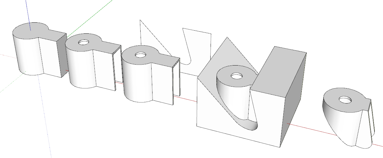
You might turn on Hidden Geometry and look at what you can see. If I had to guess I would say the author drew the plan view of the exterior of the frame, extruded it to make it 3D, used Offset on the bottom face to define the thickness of the metal and pushed the inside up. Then drew a side view shape and pushed it through the existing geometry, intersected the shapes and erased everything that isn't the frame. The slope and sharp edge at the back of the caster frame is a clue.
I'd be using Eneroth Solid Tools to do the trimming of the two shapes.
Very rough example.
-
@dave r said:
@deivis1992 said:
Just for the record: scaling up means that I need to use meters or centimeters instead of millimeters ? For example: instead of 5mm, I need to use 5 cm ? I'll look into the Dave's method as well. Thank you.
Yes. That's it. If you are working with measurements in mm, set SketchUp's units to meters. Or, if you are using "The Dave Method" work at the proper units but before you do anything that might create tiny faces (read that "holes", make component and scale a copy of it up to work on.
@deivis1992 said:
So I have exploded caster wheel but how to find out how was the frame drawn?
You might turn on Hidden Geometry and look at what you can see. If I had to guess I would say the author drew the plan view of the exterior of the frame, extruded it to make it 3D, used Offset on the bottom face to define the thickness of the metal and pushed the inside up. Then drew a side view shape and pushed it through the existing geometry, intersected the shapes and erased everything that isn't the frame. The slope and sharp edge at the back of the caster frame is a clue.
I'd be using Eneroth Solid Tools to do the trimming of the two shapes.
Very rough example.
[attachment=0:3a2n6jke]<!-- ia0 -->Screenshot - 3_25_2019 , 5_14_08 PM.png<!-- ia0 -->[/attachment:3a2n6jke]Thank you for the reply. Could you please explain how you drew that side view, all those angles, ect.,? It's not very clear for me.
-
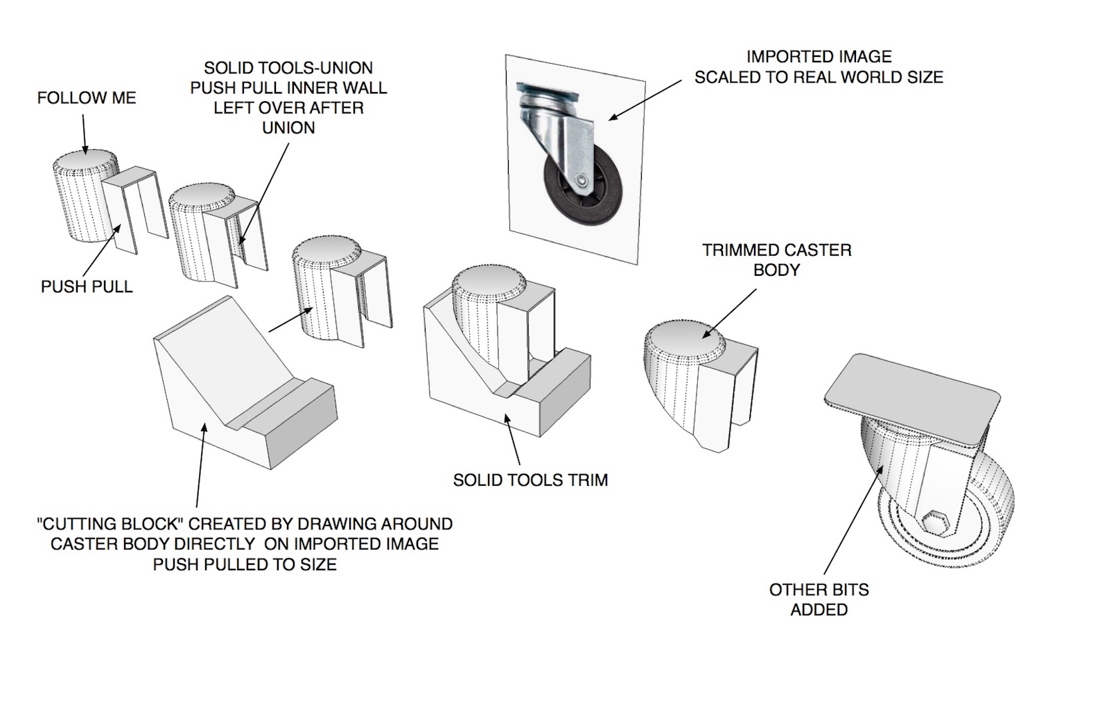
Figured I'd give DaveR a hand with explaining this. Started the model a little different than he did. Hope the images make sense. Took longer to set up the example than to model the darn caster itself
 .
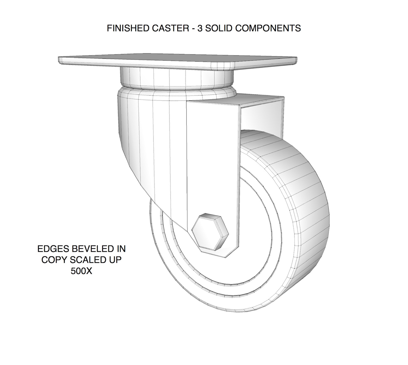
.Word of caution.. if you don't need the extreme detail like beveling edges leave them out. These type of models can get pretty heavy.
-
@tuna1957 said:
Figured I'd give DaveR a hand with explaining this. Started the model a little different than he did. Hope the images make sense. Took longer to set up the example than to model the darn caster itself
.Word of caution.. if you don't need the extreme detail like beveling edges leave them out. These type of models can get pretty heavy.
Wow, looks great! How did you drew around caster body? I am still struggling with that. Really frustrating this part is for me.

-
If I understand you right your still having difficulty with making the shape to trim with ?
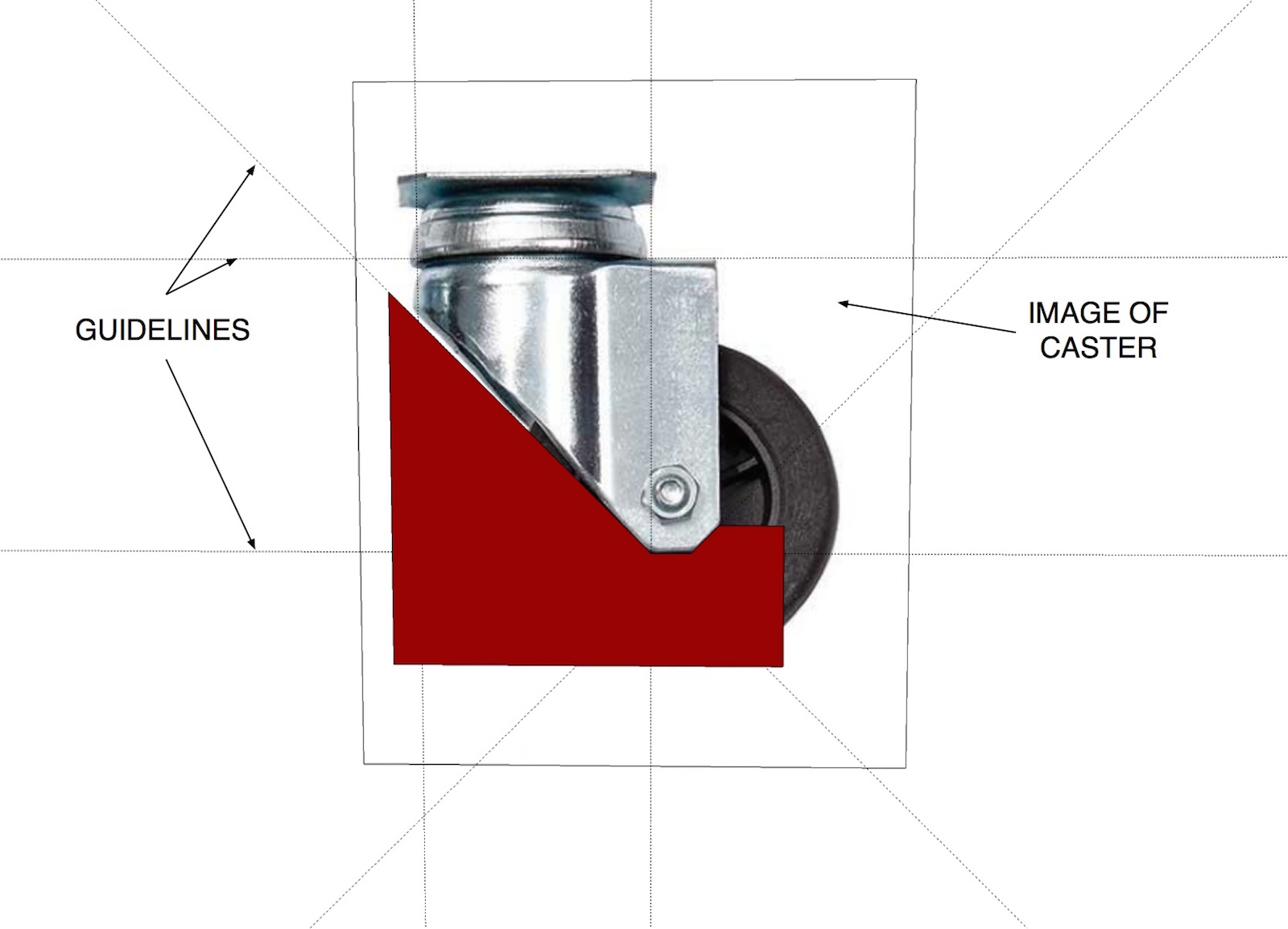
You simply draw right on the image of the caster. Place guidelines where you feel you'll need them and draw around with the line tool. I painted the face red in the image I posted so it will show up better. After you draw the shape select it and move it off the face of the image. Use push pull and make it wider than your caster body. Make it a group. Then you position it to intersect the caster body group and use solid tools to trim it up.
-
@deivis1992 said:
How did you drew around caster body? I am still struggling with that. Really frustrating this part is for me.
FWIW, I drew the caster frame starting with a circle and a few straight lines to make the keyhole shape which was then extruded to the height of the frame. I was just looking at the image of the caster you supplied so I didn't make it more elaborate like Tuna did.
Then as I described in my previous post, I used Offset on the edge at the bottom and then Push/Pull to extrude the inside of the frame up to make it hollow. I added the hole because it is there in your screen shot but if I was modeling this caster for my own use, I wouldn't bother with it.
-
@tuna1957 said:
If I understand you right your still having difficulty with making the shape to trim with ?
You simply draw right on the image of the caster. Place guidelines where you feel you'll need them and draw around with the line tool. I painted the face red in the image I posted so it will show up better. After you draw the shape select it and move it off the face of the image. Use push pull and make it wider than your caster body. Make it a group. Then you position it to intersect the caster body group and use solid tools to trim it up.
Yes, that was the thinking that I talked about. Everything is much clearer now. Do you always do that with more difficult shapes?
Thank you.
-
@dave r said:
@deivis1992 said:
How did you drew around caster body? I am still struggling with that. Really frustrating this part is for me.
FWIW, I drew the caster frame starting with a circle and a few straight lines to make the keyhole shape which was then extruded to the height of the frame. I was just looking at the image of the caster you supplied so I didn't make it more elaborate like Tuna did.
Then as I described in my previous post, I used Offset on the edge at the bottom and then Push/Pull to extrude the inside of the frame up to make it hollow. I added the hole because it is there in your screen shot but if I was modeling this caster for my own use, I wouldn't bother with it.
Hi Dave,
I could understand that part. The part I could not is shown in image below. Drawing the actual shape intersectin, get a final shape for body.

-
That was done by drawing a rectangle, a circle for the bottom curve and then some lines between the edge of the rectangle and the circle. After those were done, I erased the top part of the circle and the edge of the rectangle between the angled lines.
It's not very precise because I was just eyeballing from your image.
-
[quote="Deivis1992"] Do you always do that with more difficult shapes?
It really depends on the final use of the model and how much detail I want. Sometimes just having the approximate dimensions and "eyeballing is fine".


Advertisement