Caster wheel
-
@deivis1992 said:
Also is Sketchup suitable software for making small/detailed objects ? I keep getting a message that "Radius is too small or number of segments is too large for given angle".
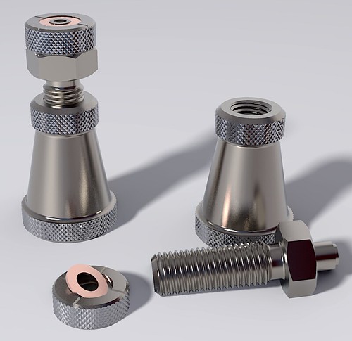
It is possible to model small, detailed objects in SketchUp. The body of this machinist's jack is 56mm tall. Although they can exist, SketchUp doesn't create tiny faces. The solution is to use the []Dave Method](https://sketchucation.com/forums/viewtopic.php?f) as pbacot indicated or work at a larger size and scale down after modeling.
You've surely noticed that SketchUp approximates arcs, circles and other curves using a series of straight edge segments. The message you report appears when you try to make a very small radius arc or circle in which those segments would be too small for creating faces. It is intended to help users avoid holes in their models and was especially aimed at models for 3D printing. Holes in surfaces prevent models from being printable.
@deivis1992 said:
In addition, is it possible to see how a part was drawn is skectchup ? when you downloaded something from warehouse ? I mean exploding a view or something ?
It depends on how it was modeled and if the individual parts were made as components or groups. If they were, you can move them away from each other so you can look at just the caster frame, for example. It is sometimes possible to suss out how the author modeled something using clues they might leave behind in hidden geometry and such. Some times you just have to guess, though.
@deivis1992 said:
Just simply create a visual of a wheel and attach it to the furniture that's the main reason.
I would never tell you not to model the caster because it would be a good learning experience. If you are interested in modeling caster or other small hardware, you should do that. In the interest of expediency, however, you might consider using a caster from the 3D Warehouse if you can find one that is close enough. Or use one as a starting point and modify it as needed. If you do choose to use one from the Warehouse in your project, don't insert it directly. Open it first in a separate SketchUp session so you can examine it and make sure it is suitable. Check its dimensions, look for unneeded detail and remove it and so on. As I wrote before, you won't need details like bearings and rivets or screws. If a caster you download from the Warehouse has those, take a few minutes to remove them and clean up the model to reduce its file size. Also check to see that face orientation is correct and fix any that are reversed. In Model Info>Statistics, Purge Unused and then save the component locally so you can import it into your furniture model.
-
Please be aware that not all models in the Warehouse are made in SketchUp and most are not good examples --at least what I've tried.
-
Peter makes an excellent point. You have to be discerning about the models you use from the Warehouse. File size can be an indicator of how much detail there is. There's probably little point in putting a 10 Mb caster component into a 1 Mb furniture model.
-
Also if you are just using them as a small visual addition they could be face me components.
So much comes down to your use case. -
@pbacot said:
@deivis1992 said:
Also is Sketchup suitable software for making small/detailed objects ? I keep getting a message that "Radius is too small or number of segments is too large for given angle".
You might want to scale up the component for models this size. I am not sure why you get those particular messages, but for many operations SU will not create small faces. However when you scale the component back down the faces will still be there.
If you are indeed using SU components you can use the Dave Method and duplicate the component then scale that second instance of the component, and work on that. The changes will also be made in the original small instance. Scale at 10-100 times larger.
Just for the record: scaling up means that I need to use meters or centimeters instead of millimeters ? For example: instead of 5mm, I need to use 5 cm ? I'll look into the Dave's method as well. Thank you.
-
@dave r said:
@deivis1992 said:
Also is Sketchup suitable software for making small/detailed objects ? I keep getting a message that "Radius is too small or number of segments is too large for given angle".
It is possible to model small, detailed objects in SketchUp. The body of this machinist's jack is 56mm tall. Although they can exist, SketchUp doesn't create tiny faces. The solution is to use the []Dave Method](https://sketchucation.com/forums/viewtopic.php?f) as pbacot indicated or work at a larger size and scale down after modeling.
You've surely noticed that SketchUp approximates arcs, circles and other curves using a series of straight edge segments. The message you report appears when you try to make a very small radius arc or circle in which those segments would be too small for creating faces. It is intended to help users avoid holes in their models and was especially aimed at models for 3D printing. Holes in surfaces prevent models from being printable.
@deivis1992 said:
In addition, is it possible to see how a part was drawn is skectchup ? when you downloaded something from warehouse ? I mean exploding a view or something ?
It depends on how it was modeled and if the individual parts were made as components or groups. If they were, you can move them away from each other so you can look at just the caster frame, for example. It is sometimes possible to suss out how the author modeled something using clues they might leave behind in hidden geometry and such. Some times you just have to guess, though.
@deivis1992 said:
Just simply create a visual of a wheel and attach it to the furniture that's the main reason.
I would never tell you not to model the caster because it would be a good learning experience. If you are interested in modeling caster or other small hardware, you should do that. In the interest of expediency, however, you might consider using a caster from the 3D Warehouse if you can find one that is close enough. Or use one as a starting point and modify it as needed. If you do choose to use one from the Warehouse in your project, don't insert it directly. Open it first in a separate SketchUp session so you can examine it and make sure it is suitable. Check its dimensions, look for unneeded detail and remove it and so on. As I wrote before, you won't need details like bearings and rivets or screws. If a caster you download from the Warehouse has those, take a few minutes to remove them and clean up the model to reduce its file size. Also check to see that face orientation is correct and fix any that are reversed. In Model Info>Statistics, Purge Unused and then save the component locally so you can import it into your furniture model.
Thank you for such a long and informative answer.
So I have exploded caster wheel but how to find out how was the frame drawn ?
Please see attached.
-
@deivis1992 said:
Just for the record: scaling up means that I need to use meters or centimeters instead of millimeters ? For example: instead of 5mm, I need to use 5 cm ? I'll look into the Dave's method as well. Thank you.
Yes. That's it. If you are working with measurements in mm, set SketchUp's units to meters. Or, if you are using "The Dave Method" work at the proper units but before you do anything that might create tiny faces (read that "holes", make component and scale a copy of it up to work on.
@deivis1992 said:
So I have exploded caster wheel but how to find out how was the frame drawn?
You might turn on Hidden Geometry and look at what you can see. If I had to guess I would say the author drew the plan view of the exterior of the frame, extruded it to make it 3D, used Offset on the bottom face to define the thickness of the metal and pushed the inside up. Then drew a side view shape and pushed it through the existing geometry, intersected the shapes and erased everything that isn't the frame. The slope and sharp edge at the back of the caster frame is a clue.
I'd be using Eneroth Solid Tools to do the trimming of the two shapes.
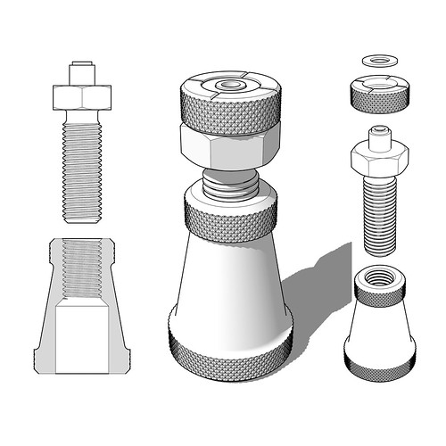
Very rough example.
-
@dave r said:
@deivis1992 said:
Just for the record: scaling up means that I need to use meters or centimeters instead of millimeters ? For example: instead of 5mm, I need to use 5 cm ? I'll look into the Dave's method as well. Thank you.
Yes. That's it. If you are working with measurements in mm, set SketchUp's units to meters. Or, if you are using "The Dave Method" work at the proper units but before you do anything that might create tiny faces (read that "holes", make component and scale a copy of it up to work on.
@deivis1992 said:
So I have exploded caster wheel but how to find out how was the frame drawn?
You might turn on Hidden Geometry and look at what you can see. If I had to guess I would say the author drew the plan view of the exterior of the frame, extruded it to make it 3D, used Offset on the bottom face to define the thickness of the metal and pushed the inside up. Then drew a side view shape and pushed it through the existing geometry, intersected the shapes and erased everything that isn't the frame. The slope and sharp edge at the back of the caster frame is a clue.
I'd be using Eneroth Solid Tools to do the trimming of the two shapes.
Very rough example.
[attachment=0:3a2n6jke]<!-- ia0 -->Screenshot - 3_25_2019 , 5_14_08 PM.png<!-- ia0 -->[/attachment:3a2n6jke]Thank you for the reply. Could you please explain how you drew that side view, all those angles, ect.,? It's not very clear for me.
-
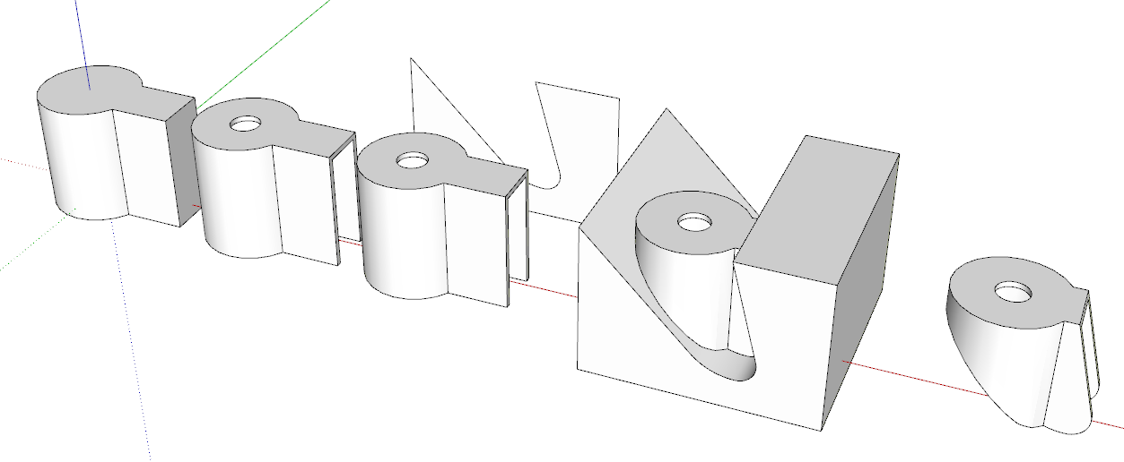
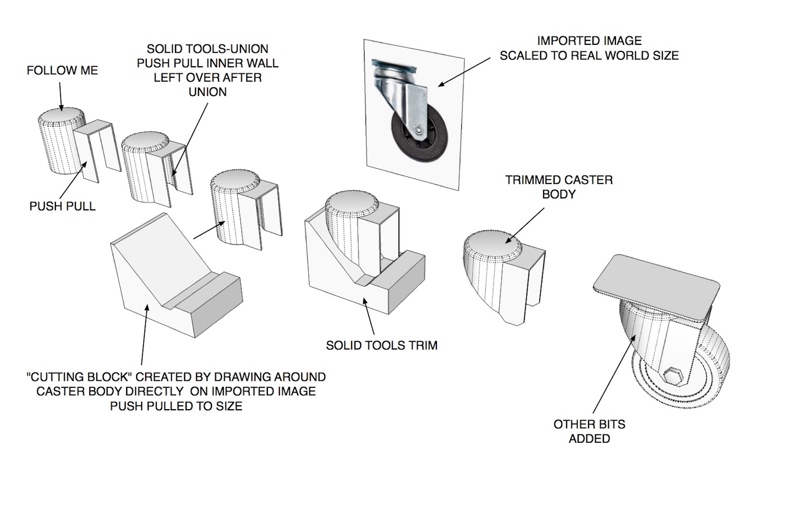
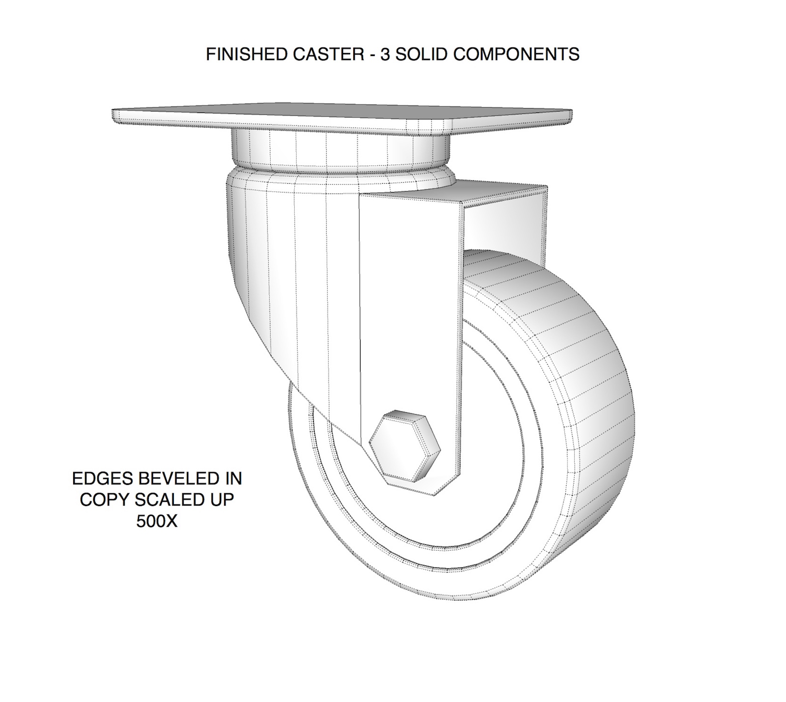
Figured I'd give DaveR a hand with explaining this. Started the model a little different than he did. Hope the images make sense. Took longer to set up the example than to model the darn caster itself
 .
.Word of caution.. if you don't need the extreme detail like beveling edges leave them out. These type of models can get pretty heavy.
-
@tuna1957 said:
Figured I'd give DaveR a hand with explaining this. Started the model a little different than he did. Hope the images make sense. Took longer to set up the example than to model the darn caster itself
.Word of caution.. if you don't need the extreme detail like beveling edges leave them out. These type of models can get pretty heavy.
Wow, looks great! How did you drew around caster body? I am still struggling with that. Really frustrating this part is for me.

-
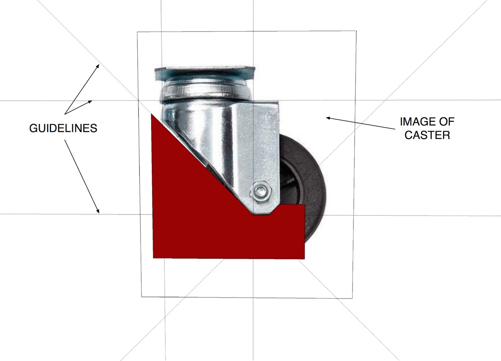
If I understand you right your still having difficulty with making the shape to trim with ?
You simply draw right on the image of the caster. Place guidelines where you feel you'll need them and draw around with the line tool. I painted the face red in the image I posted so it will show up better. After you draw the shape select it and move it off the face of the image. Use push pull and make it wider than your caster body. Make it a group. Then you position it to intersect the caster body group and use solid tools to trim it up.
-
@deivis1992 said:
How did you drew around caster body? I am still struggling with that. Really frustrating this part is for me.
FWIW, I drew the caster frame starting with a circle and a few straight lines to make the keyhole shape which was then extruded to the height of the frame. I was just looking at the image of the caster you supplied so I didn't make it more elaborate like Tuna did.
Then as I described in my previous post, I used Offset on the edge at the bottom and then Push/Pull to extrude the inside of the frame up to make it hollow. I added the hole because it is there in your screen shot but if I was modeling this caster for my own use, I wouldn't bother with it.
-
@tuna1957 said:
If I understand you right your still having difficulty with making the shape to trim with ?
You simply draw right on the image of the caster. Place guidelines where you feel you'll need them and draw around with the line tool. I painted the face red in the image I posted so it will show up better. After you draw the shape select it and move it off the face of the image. Use push pull and make it wider than your caster body. Make it a group. Then you position it to intersect the caster body group and use solid tools to trim it up.
Yes, that was the thinking that I talked about. Everything is much clearer now. Do you always do that with more difficult shapes?
Thank you.
-
@dave r said:
@deivis1992 said:
How did you drew around caster body? I am still struggling with that. Really frustrating this part is for me.
FWIW, I drew the caster frame starting with a circle and a few straight lines to make the keyhole shape which was then extruded to the height of the frame. I was just looking at the image of the caster you supplied so I didn't make it more elaborate like Tuna did.
Then as I described in my previous post, I used Offset on the edge at the bottom and then Push/Pull to extrude the inside of the frame up to make it hollow. I added the hole because it is there in your screen shot but if I was modeling this caster for my own use, I wouldn't bother with it.
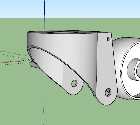
Hi Dave,
I could understand that part. The part I could not is shown in image below. Drawing the actual shape intersectin, get a final shape for body.

-
That was done by drawing a rectangle, a circle for the bottom curve and then some lines between the edge of the rectangle and the circle. After those were done, I erased the top part of the circle and the edge of the rectangle between the angled lines.
It's not very precise because I was just eyeballing from your image.
-
[quote="Deivis1992"] Do you always do that with more difficult shapes?
It really depends on the final use of the model and how much detail I want. Sometimes just having the approximate dimensions and "eyeballing is fine".

Hello! It looks like you're interested in this conversation, but you don't have an account yet.
Getting fed up of having to scroll through the same posts each visit? When you register for an account, you'll always come back to exactly where you were before, and choose to be notified of new replies (either via email, or push notification). You'll also be able to save bookmarks and upvote posts to show your appreciation to other community members.
With your input, this post could be even better 💗
Register Login


Advertisement