Medeek Electrical
-
Version 1.1.7 - 08.13.2020
- Created the Medeek Electrical UK (British Standard) toolbar, with two additional functions/tools: Draw Switch, Draw Outlet.
- Enabled the Draw Switch (UK) tool with the following switch types (MK Logic Plus): single pole, dimmer, blank.

-
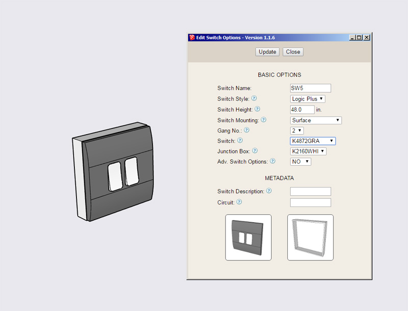
Since I am using manufacturer's part numbers to specify the switch and box with the new UK module I thought it made sense to provide a thumbnail to aid in the selection process:

-
Version 1.1.7b - 08.13.2020
- Added preview thumbnails to the draw and edit menus of the UK switch tool.
-
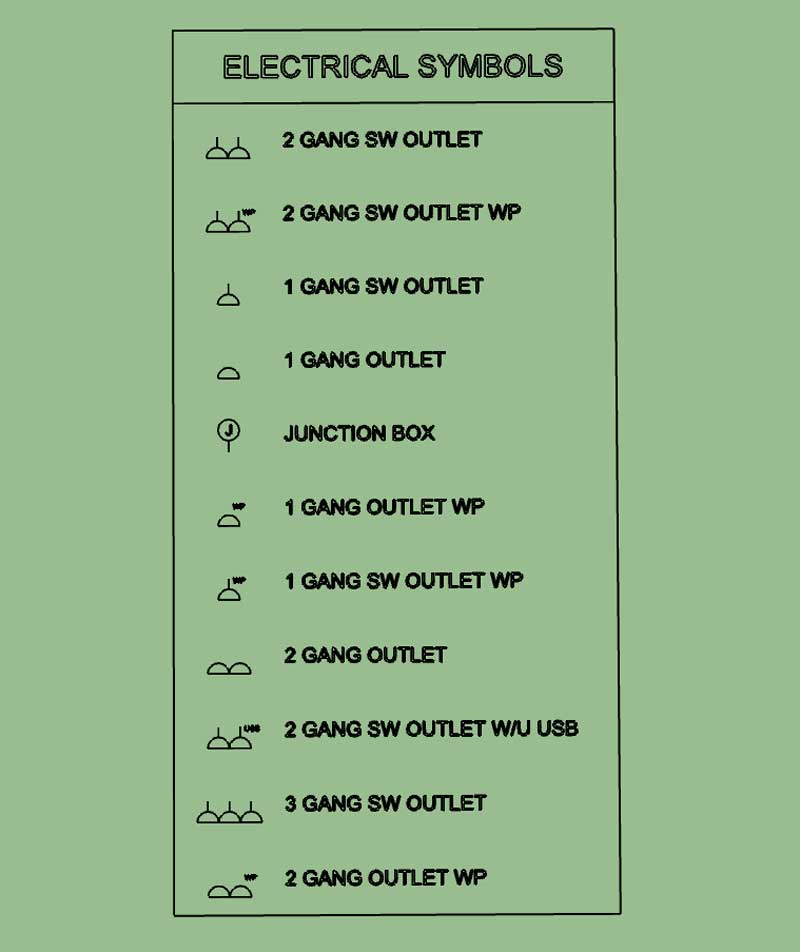
After some further digging about on the internet I really only came upon three or four reference documents for UK outlet symbols. Based on those examples here are my proposed symbols:

Please provide feedback or suggestions.
I planning on using the abbreviation "SW" for switched since I am trying to keep the length of the text in the legend to a manageable length, or I could spell it out in full.
There will probably be other outlet types (ie. fused outlets or connector outlets), but this is all I have for now.
-
Version 1.1.8 - 08.15.2020
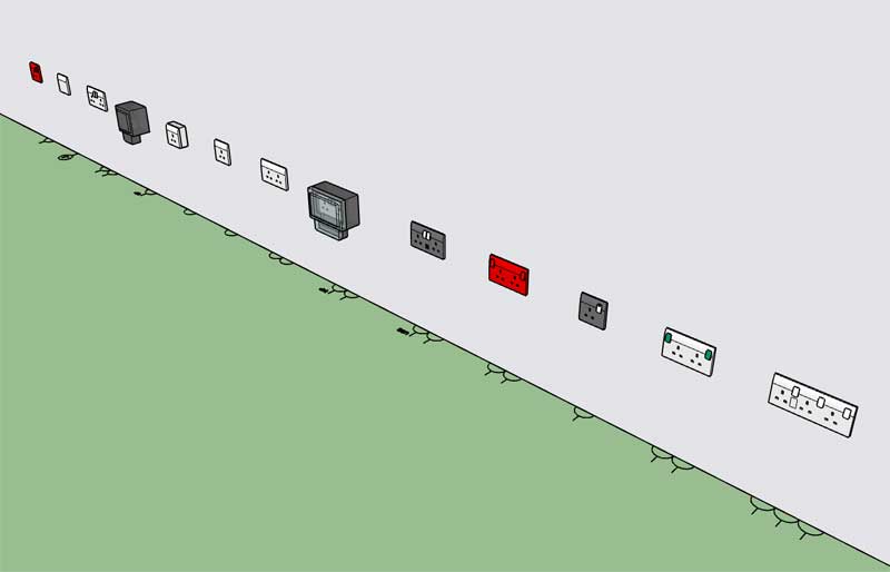
- Enabled the Draw Outlet (UK) tool with the following outlets types (MK Logic Plus): unswitched, switched, switched w/ USB, weatherproof, blank.
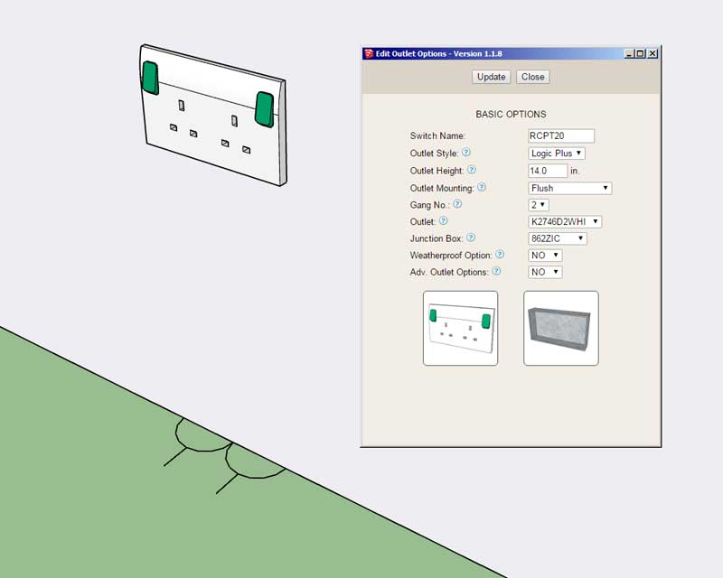
- Added preview thumbnails to the draw and edit menus of the UK outlet tool.
- Added UK outlet (2D) symbols to the Legend tool.
-
Editing a UK outlet:

-
As opposed to choosing the outlet by a code (and having the visual reference appear then), can we do the search for the outlet module by scrolling through a visual reference as well?
-
Tutorial 4: UK Toolbar
-
Version 1.1.9 - 09.10.2020
- Added optional metadata parameters for outlets: description, circuit.
-
Custom Wiring Feature:
I've been getting some requests for the ability to add in wiring.
After giving this some additional thought I think I can add in a rudimentary wiring module that will allow the user to create their own wire types. The basic parameters would be:
1.) Name: NM-B_14/3, NM-B_8/3 etc...
2.) Shape: RND or RECT
3.) Dia.
4.) Width
5.) Depth
6.) Color
7.) Bend Radius
-
The second toolbar will include a new icon for wiring:

Additionally the wiring assemblies will not be embedded into any other assemblies (ie. wall, roof, floor etc...), this way they can be edited and regenerated. I will have two context menu items for wiring assemblies: edit and regen.
-
The bend radius is the parameter that is the most unique feature of this tool. One could easily use a tool like profile builder to generate the wiring but with the bend radius the tool will introduce another level of complexity.
In some cases the line segment(s) will be too short to allow for the bend to occur, in these cases the radius will not be applied, the segments will simply be followed as is.
The wire types can be configured in the global settings of the plugin.
-
First look at the Custom Wire Library tab in the global settings:

-
Version 1.2.0 - 10.11.2020
- Added a "Refresh Licensee Data" button within the License tab of the Global Settings.

-
Version 1.2.1 - 10.14.2020
- Added a Custom Wire Library to the Global Settings which allows user defined rectangular or circular cross section wires/cables/conduit.
- Enabled the Wiring Tool with three additional context menu functions: Edit Wire Assembly, Regen Wire Assembly, Edit Wire Path.
- Added a 4th dimensioning layer specifically for wire callouts in the Layers tab of the Global Settings.
- Added the following parameters to the General tab of the Global Settings: Wire Label Callout, Wire Label Prefix, Circle Segments.
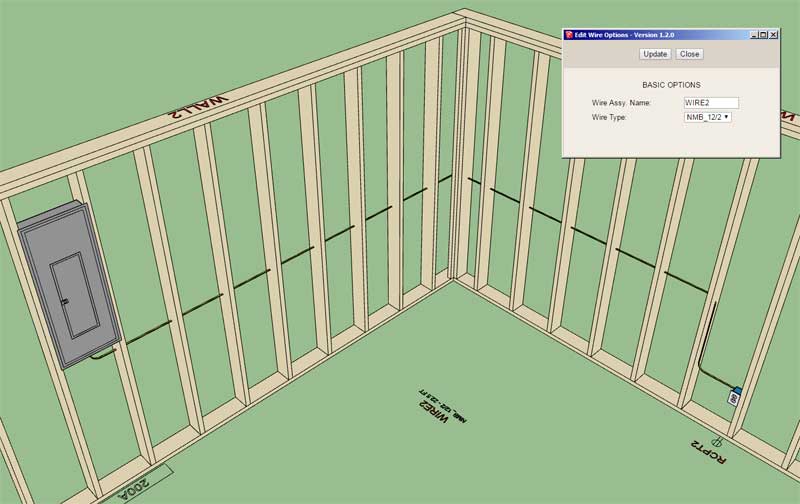
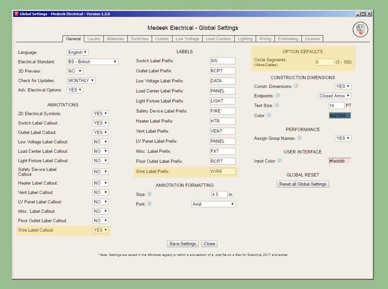
I think I need a few additional tools to round out this wiring module and make it more intuitive and efficient to use:
- Move Segment Tool (rather than having to edit the wire path directly)
- Integrate the Estimating tool with the wiring statistics
-
Quite impressive, though it didn't occur to me someone would model house wiring. Gotta be more fun than actually running it though.
-
Note that the wire callout gives the name of the wire, the type and the length.
I would tend to agree with Pbacot, I didn't think people would want to go to the trouble of modeling wires but I've received enough features for this request that I decided I should include it as part of the plugin.
For round wires I have the "circle segment" parameter which allows ones to decrease the number of segments in order to keep the polycount down in the model.
The draw tool needs a feature or switch which allows one to simply select a pre-drawn polyline (of edges) rather than picking points.
-
Version 1.2.1b - 10.15.2020
- Draw Wire Tool input extended to two options: Points, Edges
Tutorial 5 - Wiring (11:15 min.)
-
Just for fun I created some "wire" sizes at your typical HVAC duct sizes and then laid out some geometry (polylines) with the help of the SketchUp grid extension:

The only thing I could not draw with the wire tool was the rectangular reducer shown in blue.
HVAC (duct work) is fairly straight forward in my opinion however there needs to be a few more specific parts and pieces in order to terminate and make transitions. So there would need to be a separate tool (and library) for common size reducers, boots and grilles.
I'm not really an HVAC (mechanical engineer), I've done a little work in the field about 15 years ago while doing some contract work at BYU, but then again I'm not an electrician either and look how far this plugin has come. I guess it just takes some interest and a desire to learn, but I do think HVAC is a bit more involved than Electrical.
-
@medeek said:
Just for fun I created some "wire" sizes at your typical HVAC duct sizes and then laid out some geometry (polylines) with the help of the SketchUp grid extension:

The only thing I could not draw with the wire tool was the rectangular reducer shown in blue.
HVAC (duct work) is fairly straight forward in my opinion however there needs to be a few more specific parts and pieces in order to terminate and make transitions. So there would need to be a separate tool (and library) for common size reducers, boots and grilles.
I'm not really an HVAC (mechanical engineer), I've done a little work in the field about 15 years ago while doing some contract work at BYU, but then again I'm not an electrician either and look how far this plugin has come. I guess it just takes some interest and a desire to learn, but I do think HVAC is a bit more involved than Electrical.
An useful HVAC tool would be nice, it doesn't have to do the complex calculations but rather be useful as a tool with the options (size of ducts, grilles, etc.) to be set/chosen by the end-user whilst being able to handle the transformations automatically.
Advertisement


