Hidden lines not visible in Layout
-
When I insert a viewport into layout it initially shows correctly with the hidden lines visible as dashes. The scene is set to Last used ....
When I then make the scene specific to what I know is the last scene I do not see the hidden lines as dashes or anything else.
After much poking around I see that when initially brought over the "last used view" has a modified style used in the scene. So How do i figure out what that modification is so i can put it in tho the scene?
The images attached show:
2017-09-19_14-04-02.png: Shows skp for the scene in question ("Bookcase - Moving Outer Left") as I saved it. I have the style tray showing in this image and that confirms that style "WoodworkingPlans01" was selected and with 5 snapshots of the other settings for the superimposed.
[highlight=#ffffbf:2o5cj57t]And yes I did update the style and save the skp and do a document update in layout - in fact I even created a new document and newly inserted just to make sure.[/highlight:2o5cj57t]
2017-09-19_14-04-09.png: This shows the viewport after being inserted into a new layout document. Note that "Last Saved ..." is the scene and the style is "(Modified) WoodworkingPlans01"
The remaining images show what happens when I change the scene from "Last Used ..." to "Bookcase - Moving Outer Left" - which implies the unmodified "WoodworkingPlans01"
2017-09-19_14-36-38.png: On first selection of scene "Bookcase - Moving Outer Left" the selection remains "raster" and no image appears.
2017-09-19_14-39-21.png: Switching to "Vector" the image appears but with no hidden lines
2017-09-19_14-39-53.png: Switching to "Hybrid" the image appears but with no hidden lines
2017-09-19_14-40-25.png: Returning to "Raster" no image appears
2017-09-19_14-41-36.png: Back to "Vector" the image appears but with no hidden lines AND NOTE THAT the unmodified "WoodworkingPlans01" is in effect
-
I don't see any images with your post but it would be best if you share the LayOut file. If you don't want to make that public, send it to me in a private message and I'll keep it private.
From what I can glean, the main problems stem from not doing as I advised earlier.
-
Sorry I forgot the screen grabs
Also sent a skp and layout file in layout see page 2 and change the scene from "Last Used ..." to "Bookcase - Moving Outer Left" to replicate what happened in
2017-09-19_14-36-38.png: On first selection of scene "Bookcase - Moving Outer Left" the selection remains "raster" and no image appears.
Thanks for your time and interest!
-
I am sorry i forgot to attach. I have now done so and have included the skp and layout files. On page 2 of layout you will find a viewport with the "Last Used ..." view.
If you will change it to "Bookcase - Moving Outer Left" you should see results similar to those reported in image 2017-09-19_14-36-38.png:
PS I thought I sent this last night - but I guess i did not if I did please forgive double submission.
-
-
I'll look at your files when I get home from work. How late are you available?
-
I will make time for you whenever.
-
OK. Finally a few seconds to look at your LO file but I have to run again.
First, your "hidden lines" are actually Back Edges--a Face Style setting. Back Edges are a raster thing so they will not show when you render the viewport as Vector or Hybrid. In Vector and Hybrid rendering, only visible edges are displayed as vector lines. When I want to show hidden lines as dashed in LO, I have Back Edges turned on for the scene(s) in SketchUp, render in Raster and trace the back edges with LO's Line tool set to draw dashed lines. Then I render the viewport as Vector when I'm finished tracing. I end up with something like this:
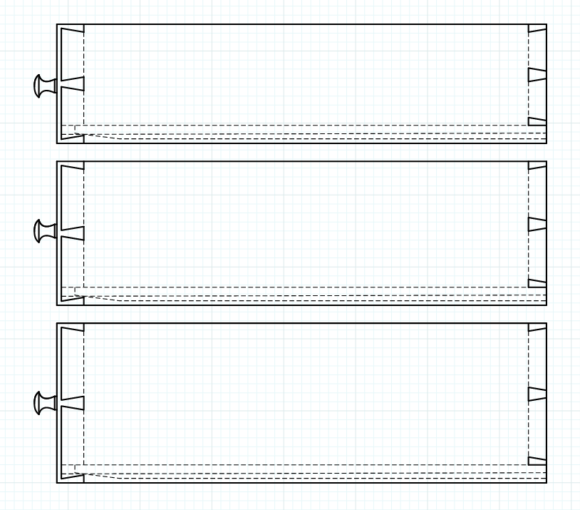
There are other things in your LO file as well as the SketchUp that need to be addressed when I get back.
-
Dave R
Your private message was very very helpful! I now see why i was having some problems. Particularly Layers! Your suggestion is simple: Groups and components on layers<>0 everything else even when within a group or comp on layer 0. (perhaps my experience as an object oriented programmer caused me to do otherwise).
I cannot reply privately yet as i am still a newbie. My email is dan dot pressman at ntuple do com
A couple of things:
While I understand your solution for the hidden edges (which are as you point out back edges in my case) what I do not understand is why on first insertion of the "Last Used ..." scene the back edges are visible as dashes?
So there is a difference between a back edge and a hidden line. Perhaps this would be a great topic for someone to post. In the meantime this is my understanding: OK my father always said that you do not understand something unless you can teach/explain it - that is what I found when trying to write up my understanding.
Attached please find a skp file I was using to try to write this up. I was wondering: a back edge is a special case of a hidden line. It is one that is within the same solid object or alternatively within the same group or component.
Part of my problem may be that I have modified the original Hidden line style. Is there a way to return to the original as delivered or could you let me know the settings?
I have leaned on you quite a bit but it has been great for me and i really appreciate it. Please answer only if you have time.
Thanks
-
Ok I went to make my viewports transparent as you suggested and actually found your post here http://sketchucation.com/forums/viewtopic.php?f=79%26amp;t=63380 confirming how this is to be done. It did not work. Is this because of the Layout 2017 bug seen here https://forums.sketchup.com/t/transparent-style-views-rendering-opaque-in-layout-2017/35331/10 or am I doing something wrong (the sketchup background was set to white)?
Thanks again
-
@unknownuser said:
I now see why i was having some problems. Particularly Layers! Your suggestion is simple: Groups and components on layers<>0 everything else even when within a group or comp on layer 0.
Layers is probably not the best name for the visibility control in SketchUp. Layers, as used by other programs including LayOut, imply sheets of transparent film or velum onto which different objects are placed to keep them separate. In SketchUplayers really have just one function and that is to provide visibility control. There is no separation. That is done by wrapping geometry in group or component containers.
You should never have any need to chase the layer you're working on. Leave Layer 0 active at all times. When you draw new geometry, it goes on Layer 0. When you edit a component or group, you'll be working on Layer 0. Even when you assign the components to other layers, when you are editing the contents of the container, you are editing on Layer 0.
@unknownuser said:
I do not understand is why on first insertion of the "Last Used ..." scene the back edges are visible as dashes?
When the first viewport is created in LO, it is rendered as Raster. The style you've selected in LO includes the display of back edges so they are visible. Back edges are a raster display of those edges that would otherwise be hidden behind faces. In Vector render only vector edges are displayed so the back edges are not. They are not displayed in Hybrid render either for the reason mentioned by Trent in that thread you refer to.
@unknownuser said:
So there is a difference between a back edge and a hidden line.
Well, not really. Hidden lines are those that can't be seen, of course. Back edges are just SketchUp's way of making them visible. Turning them on is just a modification of whatever style you happen to have selected. X-ray is similar but it also displays those faces that are behind the ones closer to the camera.
I use the back edges display to show me where to draw dashed lines in LO to indicate hidden lines as in the drawers in my earlier post or here in the view of the legs for the case shown below.
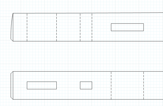
With Back edges turned on in the style and the viewport rendered as Raster, I was able to see the edges of the through mortises to trace them with LO's Line tool. After I finished tracing the back edges, they are no longer needed. Rendering in Vector gets rid of them and gives my the vector lines I want. The dashed lines are the hidden lines. Hidden lines are used to represent surfaces that are not directly visible in the orthographic view. Without hidden lines all information about the features that are not directly visible would be lost.@unknownuser said:
I was wondering: a back edge is a special case of a hidden line. It is one that is within the same solid object or alternatively within the same group or component.
Back edges are just the edges which are occluded by the faces more in the foreground. They don't have to be in the same component or group. For example, this is the 3/4 view of a model I made for plans done in LayOut.
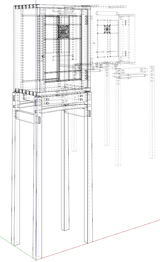
All of the copies of the components position behind the assembled copy of the model are visible by the back edges being displayed.
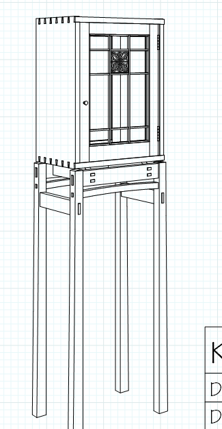
Below is the same view in LO after rendering the viewport as Vector. The components in the background are no longer visible because I've drawn a "scrim" to hide them. I could put those copies of the model components on separate layers from those in the assembled model but I find it easier to leave all the copies of the legs on one layer and all the door components on another layer. The analog part of my thinking makes the scrim an easy thing. Or maybe it's my time working in theater.
@unknownuser said:
Part of my problem may be that I have modified the original Hidden line style. Is there a way to return to the original as delivered or could you let me know the settings?
First, you might be getting the Hidden Line face style name confused with the hidden lines we've been talking about above. The Hidden Line face style is contrasted with Wireframe. In Wireframe, all edges are displayed and, as you can easily imagine, that can create very cluttered and difficult to read drawings. Hidden Line face style displays faces so that those edges behind are not visible. This face style uses the background color on the faces so no textures and there's no shading on faces.
In the Styles window you can choose the Default Styles collection in the drop down list and select the Hidden Line style.
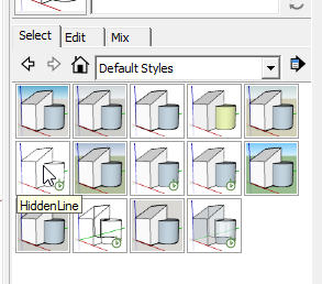
I probably missed something but hopefully this gets you a little farther down the line.
-
Wow. Great help! Dave's ended up writing a full article.
-
Unbelievably great answer. I shall read it multiple times to make sure I get it all.
-
Thank you, gentlemen.
-
I'm a little confused. How can two different styles exist on one skp screen? Or is it a LO screencap with two overlapping VP's with each having different styles? The axis lines makes me think the former.
-
Are you referring to the different appearance between the assembled model in the foreground and the exploded one on the background? Or are you talking about the different appearance in the screen shot with the axes visible and the one without?
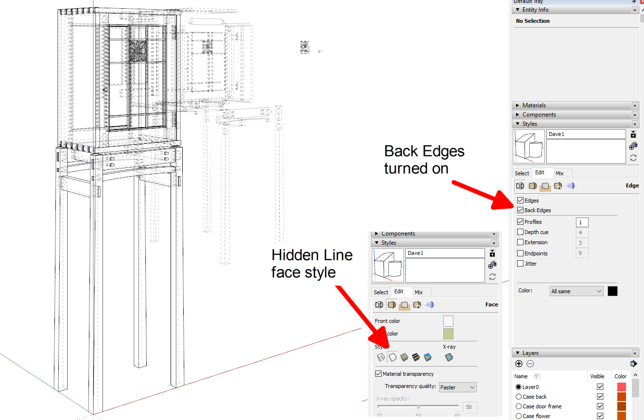
If it's the former, there's only one style being displayed; Hidden Line with Back Edges turned on. Theres a large surface between the two copies of the model so when rendered as Vector in LO, the components in the rear are not visible.
-
see below.........
-
As I said, that's the view in the SketchUp file. There is only one style being displayed. It isn't possible to show more than one style in a single scene in SketchUp.
-
I agree. So how are two different styles being displayed? What am I not comprehending?
-
What two different styles? There's only one style shown in that screen shot; Hidden Line with Back Edges turned on.
@pipingguy said:
What am I not comprehending?
I can't figure out how to make it any more clear.
Advertisement


