Medeek Wall Plugin
-
Version 0.9.9o - 11.26.2018
- Completed the Stairs tab within the global settings.
- Added the ability to draw a "Clearance Envelope" with an additional global parameter for specifying the minimum headroom.
- Added a Building Code layer and an Engineering layer to the Layers tab of the global settings.
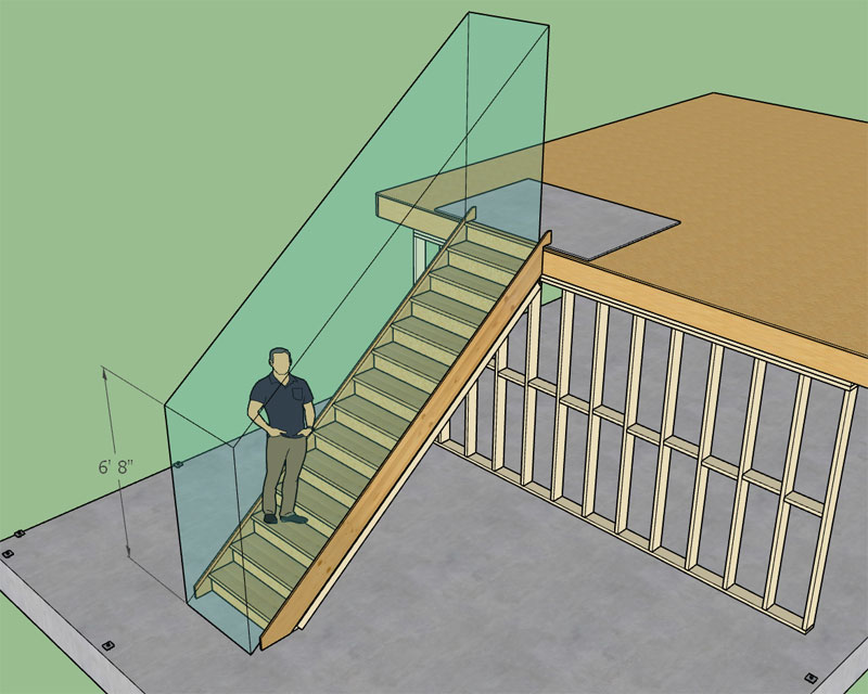
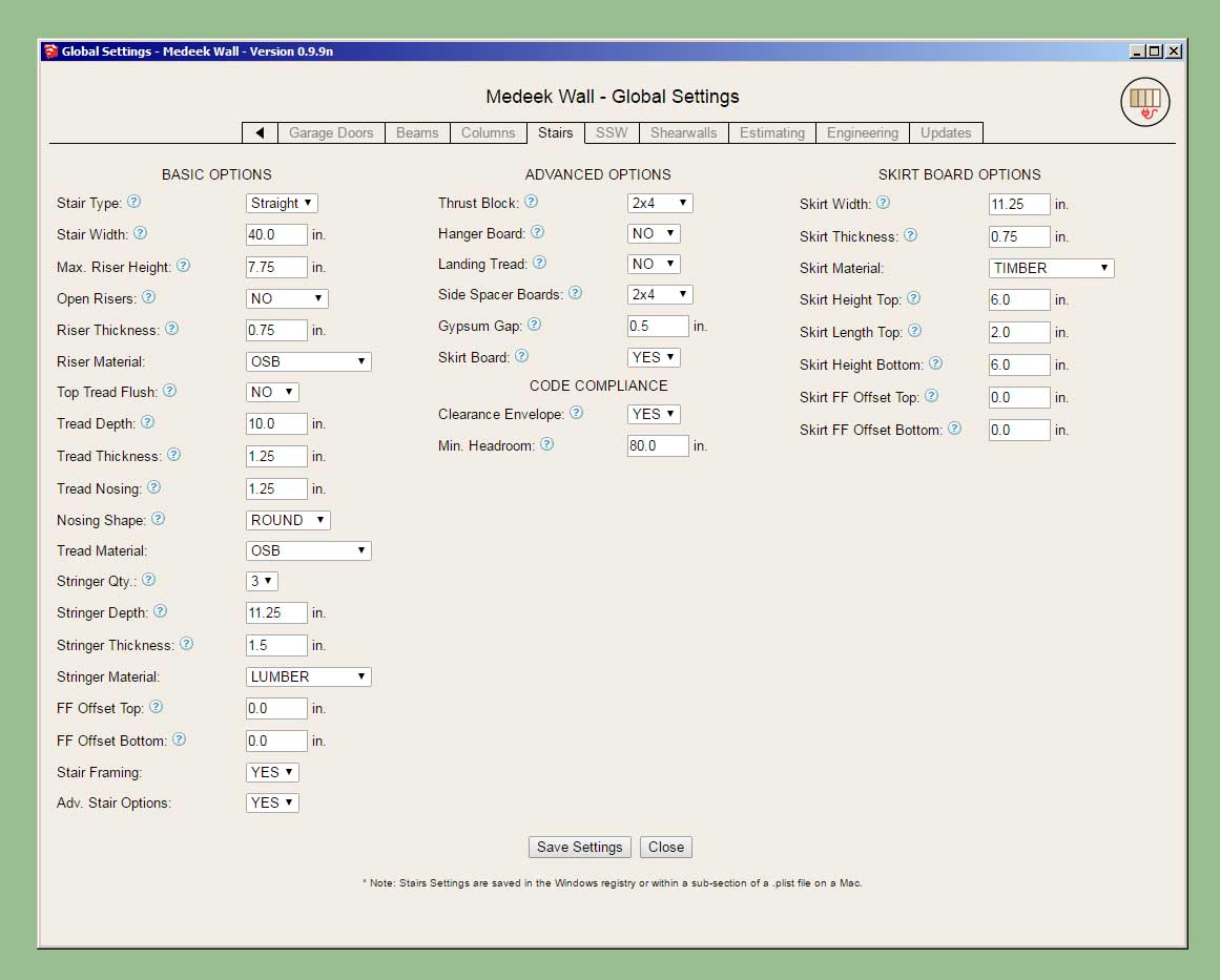
The clearance envelope (if enabled) is placed on the "code" layer. For future reference all code related items and warnings will be placed on this layer. The engineering layer will be used for engineering callouts, warnings and other related items.
The envelope is placed exactly and if the nosing is rounded then the envelope is translated a specific amount so that the tread line is tangent to the nosing. If anyone is interested the horizontal translation is given by this expression:
x_trans = r/tan(theta) - r/sin(theta) + r
where:
r = radius of the bullnose or 1/2 tread thickness.
theta = angle of stringer from the horizontalHopefully the clearance envelope is useful to designers who want to check that their framed openings for their staircases are code compliant.
-
it looks like you'll be running out of alphabet before you run out of enthusiasm
-
@juju said:
it looks like you'll be running out of alphabet before you run out of enthusiasm
I know, I really need to roll to Version 1.0.0, but I don't want to do that until the gable wall module is complete and it still has some minor issues that need working out so now I'm over halfway through the alphabet as I finish putting out other fires and a few other minor features.
As I was working on the globals for the stairs this afternoon I realized that I still have not completed the global settings for the beam module, so much to do.
I also want to get the multi-layer gypsum feature enabled, I may attack this before releasing 1.0.0, we will see.
-
Now that I'm about halfway down this rabbit hole (stair module), I should probably go a bit further. Most stairs need a hand rail:
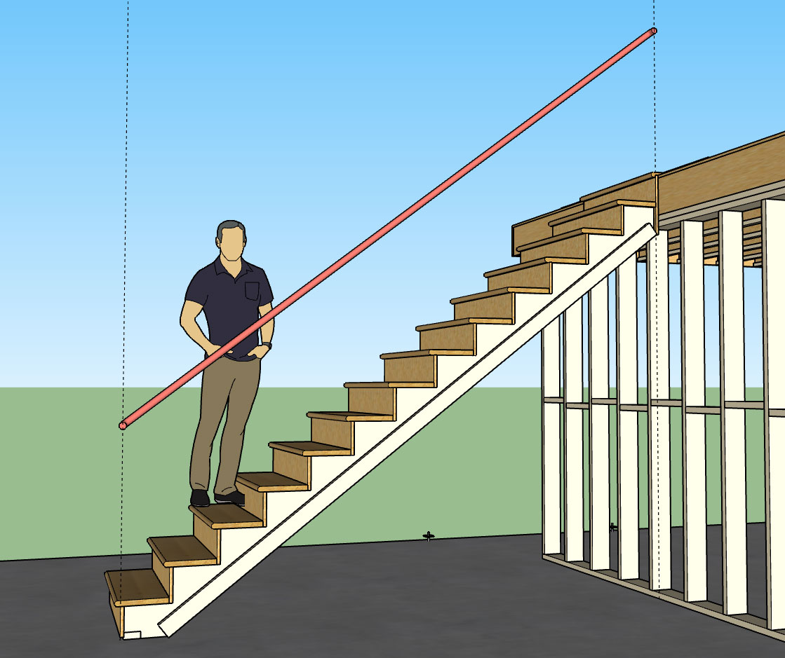
Additional advanced option: Handrails (Yes or No)
Then the handrail options shall be:
1.) Profile: Circle, Square, Custom1, Custom2 etc... (or any user defined profiles from sub-folder)
2.) Position: Left, Right, Both
3.) Height: 36" (default), vertical distance from tread line to top of handrail.
4.) Size: 1.5" (default), only applicable to circle and square profiles.
5.) Clearance: 1.5" (default), distance from inside edge of handrail to wall (gypsum).
6.) End Treatment: Cut/Vertical/Return (return shown above)
7.) Handrail Material: Default materials and custom materials from libraryI think these seven parameters are enough to define a basic handrail(s) for a straight run of stairs as shown. The option to have a vertical end treatment will allow the user to insert newel posts, however I am not really giving the option to customize where exactly the handrail will terminate so there may be some manual editing required.
With regards to manual edits, similar to the wall assemblies, the user can include custom groups or components within the stair assembly group and have them retained simply by including the text "custom" or "CUSTOM" somewhere in the instance name. If the stair assembly is then edited or regenerated by the plugin these custom entities will not be blown away but will maintain their position and properties within the main group. So theoretically one could insert any number of items such as balusters, newel posts, additional molding etc...
-
Handrails, and even the simplest balusters are a great deal of work, given working with angles and specially fit components--- and automating as possible is a great help. I'd say cover some simple scenarios. As more specific work is required, the modeler will have to take over. For building documentation, a simple stair should be sufficient.
-
There have been a lot of upgrades the last few months and as many of you know when you upgrade you lose your custom materials and also your presets.
The problem with the way it is currently setup is that this data is being stored in sub-folders within the plugin folder. When you uninstall the plugin the Extension Manager will blow away the entire plugin folder and also all of the custom data within your sub-folders.
Currently to maintain your custom library copy the sub-folder "library_mats" in its entirety to some other location on your computer. Once you've installed the updated version then copy your library_mats folder back into the plugin folder overwriting the default library_mats sub-folder installed by the Extension Manager. This will restore all of your saved custom materials and associated JPEG and PNG images.
This same method can also be employed for your wall presets, by copying the "preset" sub-folder and restoring it after an upgrade.
Please feel free to contact me directly via email or phone if you have further questions on this matter.
-
I will include some typical handrail profiles:
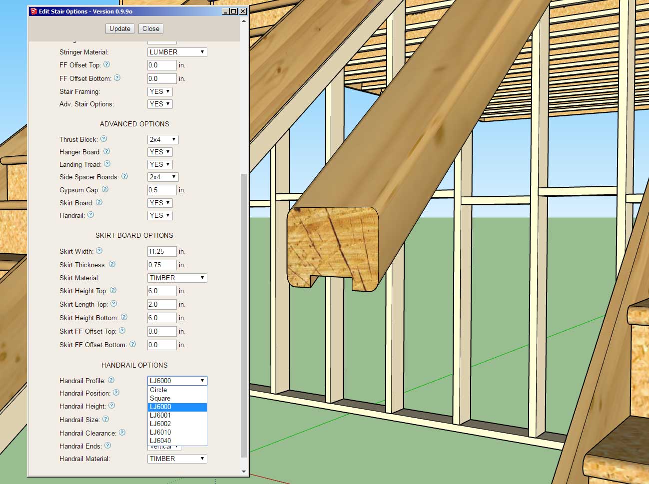
The part numbers shown are from LJ Smith and should coincide very closely with their exact geometry from their shop drawings:
I have contacted them in hopes that they can provide me exact DXF or even SketchUp files so that I can include their full handrail profile line within the library.
Adding your own custom profiles is as simple as dropping your SketchUp files into the library/handrail sub-folder.
If you have some accurate profiles that you would like added to the plugin please contact me, I reserve the right to edit any profile for accuracy and/or not include it.
-
I think that wood has too many checks in it for use in a handrail! LOL, the level of detail is fantastic!
-
Some of these profiles are rather complicated and will add a bit of weight to the model but surprisingly the performance was much better than expected:
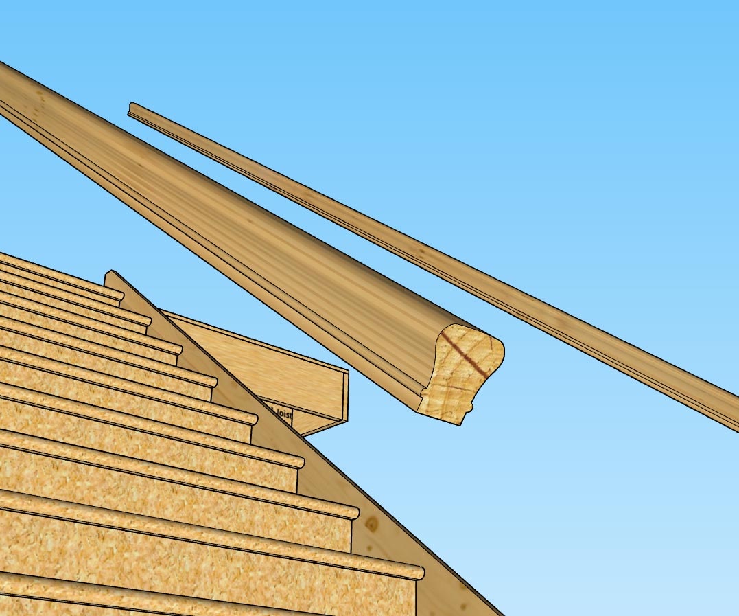
A good example is the LJ6010 profile shown above, with something like 80 line segments making up the profile.
On a related note I am just about to wrap up the handrail piece of the stair module, however I am looking at the end treatment where the user selects the "RETURN" option.
For a circle profile I typically see a radiused return rather than just a 90 degree return however I am curious as to what the preference is or if there is a typical solution here.
-
The final handrail design will most probably differ from what you have available, meaning they will most probably end up being replaced by the modeler in the end. Having a few basic options (low poly) available will probably be helpful but rather focus on the core functionality of the extension and turn the handrails into components for ease of replacement.
-
@juju said:
The final handrail design will most probably differ from what you have available, meaning they will most probably end up being replaced by the modeler in the end. Having a few basic options (low poly) available will probably be helpful but rather focus on the core functionality of the extension and turn the handrails into components for ease of replacement.
You are probably correct in that. I'm not wanting to delve too deeply into handrail profiles, just a few basic or popular ones. The user can upload any profiles they like so the flexibility is already there. My big issue right now is debugging the module in metric templates. It never fails, I get everything wrapped up in imperial units and then I switch to a metric template and there is always something amiss. I will probably take me the rest of the night to verify the updates to the stair module in metric, but I'll get there.
-
Version 0.9.9p - 12.01.2018
- Added handrails to the stair module.
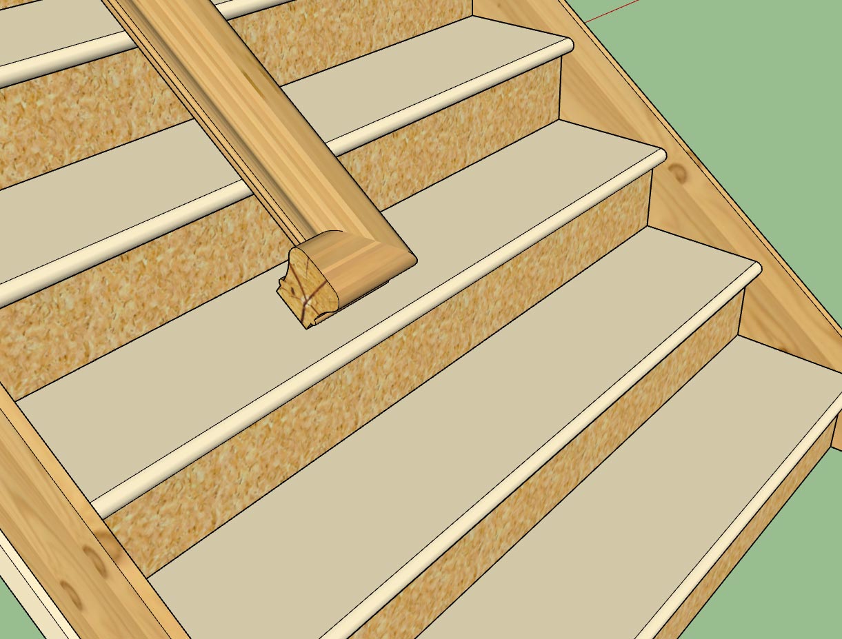
I rewrote a good chunk of the stair module this evening so this release probably resolves some additional issues with metric templates, as such I consider this version a critical update.
-
I've been looking at a lot of stairs and handrails the last couple of days and I've noticed that at that the top of a run of stairs with open treads the handrail often terminates in a single riser or two riser gooseneck. Usually the two riser gooseneck is used where the handrail takes a ninety degree turn at a landing and then proceeds up another flight of stairs.
The single riser gooseneck is a bit confusing to me though. I guess it is used so that the handrail can transition to the landing rail height before it encounters the landing newel post.
Using a follow me algorithm is really not to difficult to generate the gooseneck:
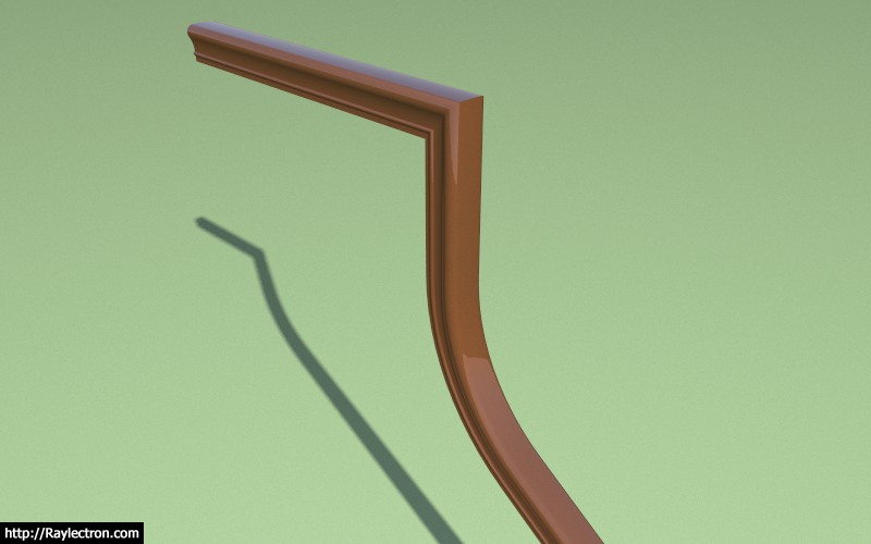
What is the typical radius of the gooseneck (up-ramp)?
I've found some interesting and helpful information here:

Ordering Specifications for Fittings for Your Stair Remodel or Project
Follow these ordering specifications for fittings. Ordering stair parts can be complicated, but we're here to simplify your next stair remodel or new project.

Direct Stair Parts (www.directstairparts.com)
I was wondering what to do about a handrail on a partially open stairs, now I know:

P.S. After some further reading it appears that a 4" difference in height is fairly typical between the landing/balcony rail height (38") and the stair handrail height (34"). This explains the need for the gooseneck fitting. I learn something new everyday with this plugin.
-
This last week I've also had quite a few inquiries about including metal studs (CFS) within the plugin.

Unlike wood framing, metal framing (studs) has a more complex profile (c-shape) with numerous cutouts for wiring/plumbing.
Could one represent metal framing with a simple rectangular member (like wood) but somehow texture it in such a way so that it looks like a metal stud? Would this be acceptable to those designers that utilize metal framing?
What level of modeling detail is optimal for metal framing?
If you add too much detail and the model becomes heavy. Obviously one would not show every bend and corrugation in a steel stud (added to increase stiffness), however even modeling the stud as a c-shape with a lip involves quite a few more polygons than a simple rectangle profile (12 faces vs. 4 faces).
Then there is also the possibility of not modeling it as solid at all but just as edges and faces, so that the thickness of the steel is not represented. This would certainly cut down on the number of polygons but would break from my long standing practice of representing everything as 3D solids.
I typically use the pushpull or followme method to generate geometry within the API, however an edge/face type model would require a new approach to modeling.
I am open to suggestions.
-
Don't do a lot of metal, cut I think a simple C profile (e.g. for the stud shown) is sufficient. I don't know if you need the cutouts since you don't show wiring (yet). The thing is that for plate/stud and all connections it is very different. I don't know what use a rectangular illustration would be. I think you are into a whole different sub-routine with steel. The graphic representation is going to be more difficult as steel often looks like "nothing" in detail drawings unless drawn carefully. I would tend toward simle extruded shapes with thickness, but not sure that's feasible with the final poly count. It should double the number of faces for your framing.
-
Until someone sends me a model of a wall with steel studs, track and a couple of openings with headers etc... I will probably put this on the back burner for now. At this point I don't have enough information in order to properly add steel framing to the plugin. More study will be required.
On a related note, what steel stud manufacturer(s) is the most commonly used for residential and commercial construction?
-
-
Version 0.9.9q - 12.03.2018
- Enabled "Over-the-Post" termination (single rise gooseneck and starting ease) for all handrail profiles.
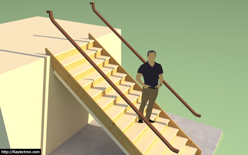
The utilization of this termination option won't really become important until I setup open sided stairs with the accompanying newel posts and balusters.
Also note that the delta Z for the starting ease and also the gooseneck is plus 4" for now, at some point I will probably want to allow the user to customize this height differential(s), but in the US market 4" seems pretty much standard.
View model here:
3D Warehouse
3D Warehouse is a website of searchable, pre-made 3D models that works seamlessly with SketchUp.
(3dwarehouse.sketchup.com)
-
I'm not even sure what to call this next tool that I am considering.
Perhaps the Blocking Tool would be the appropriate name. Basically I need to have a tool that will allow the designer to insert various/miscellaneous elements throughout the model. They may want these elements within a wall panel assembly (group) or outside of any group. The use of this tool would be primarily for additional studs or blocking.
The parameters would be:
Edit menu only:
Length: models units
Rotation: DegreesDraw and Edit menus:
Size: CUSTOM, 2x4, 2x6, 2x8 etc...
Depth: in. or mm (grayed out when standard size selected above, available when custom size selected)
Width: in. or mm (grayed out when standard size selected above, available when custom size selected)Category: BLOCK, STUD, JOIST, POST
Level: 1, 2, 3, 4, 5, 6 (this parameter will be implemented in the future for wall panels, stairs and beams as well)
Material: LUMBER, LUMBERPT (custom materials from global settings as well)
Framing: 2D, 3D
If the elements are inserted within the wall panels, they must be retained during a regen, not a problem since I already have that issue worked out.
These elements will be fully parametric.
Are there any additional options or parameters that anyone else would like to see made available with this feature?
-
This tool will create simple rectangular members only. Which means I will probably remove the POST category since stand alone posts will require a whole host of other features such as wrapping and associated base and cap hardware.
I’ve had some feedback that this feature is probably not needed at this time, but I’ve also had some comments specifically requesting it. Before I progress any further feel free to voice your opinion on the matter. This is really quite a small module and most of the code will be recycled from the beam and stair modules so I don’t anticipate taking more than 48 hours to complete it however I don’t want to invest time into a feature that will rarely be utilized.
Ultimately the plugin is for you, not for me. I don't design houses anymore, I just design the software that designs the houses. As such your opinion of what tools are made available carries more weight than mine does.
Advertisement
