Creating a Solid with a set of points
-
I'm sure someone has asked this question before but my ignorance with SketchUp has me asking anyways. I normally create a solid in my plugin by specifying a face and the using the pushpull feature to make it 3D. However for more complex geometry it would be easier to just specify a set of 3D points that are the vertices of the intended solid and have SketchUp generate it that way. Is such a thing possible?
-
Yes.

For example see my Extrude tools or Fredo's CurviLoft...
BUT, your code needs to break down the face creation into bite-sized chunks.
Because All the points defining one face will need to be coplanar.
Three points always are coplanar.
Making all the edges and then adding faces to them is likely to create unexpected 'internal' facets etc, so you need a clear plan of attack before starting...
Also to bear in mind is making faces with holes in them can become complex [e.g. perhaps make the face in the hole then the donut then delete the hole] -
Since this is in the developers' forum, also have a look at the PolygonMesh class in the Ruby API.
-
If you make the timber parts as extrusions that are pushpulled square-ended objects, then you can always 'miter' the splayed ends after that.
You can determine a suitable length vector to offset some vertices along the main plane of the truss's booms.
Use this for spaying one end at a time:
entities.transform_entities(translation_transformation, vertices_array)
or collect all of the needed vectors [if they differ] and their matching vertices, and do it in one go:
entities.transform_by_vectors(vertices_array, vectors_array)Alternatively... consider adding a temporary canted face [or 3d block], inside a group [positioned and angled to intersect the end of the boom etc] and use "intersect_with" that with the boom. With some code you can see that part of that boon lies 'behind' the face and erase those edges, thus trimming the end off etc, as if using the solid-tools themselves...
-
Specifically I am working on my Truss Plugin so that I can create hip rafters. Common rafters are easy since I just draw the profile and then pushpull it to create the 3D geometry. Hip rafters are slightly more of a challenge because of the beveled cuts at the intersection with the ridge and the fascia. I've thought about using the solid editing features of SketchUp but that would limit my plugin to only those users of the PRO version of the software so that is a no-go.
A typical hip rafter at the fascia would look something like this:
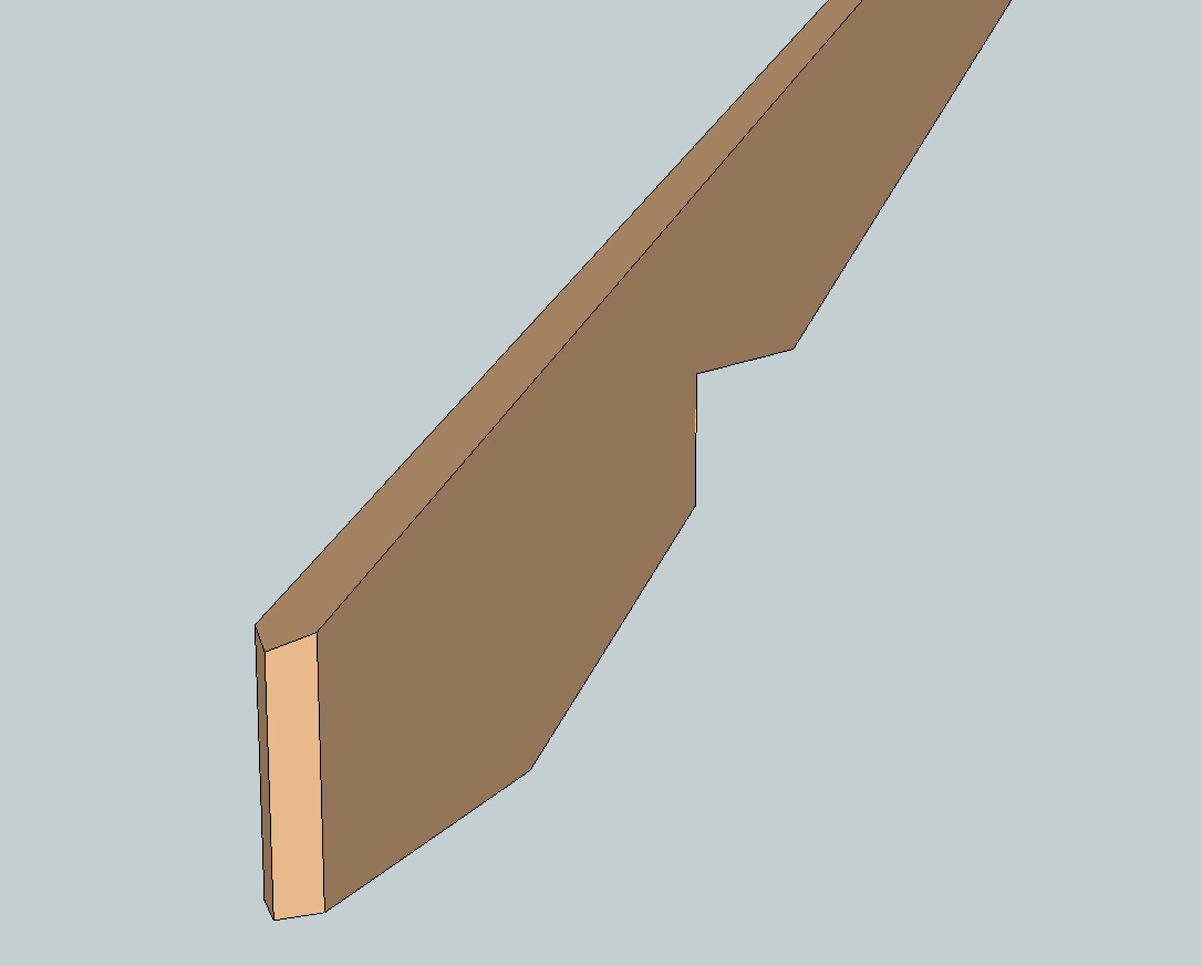
Manually I can create this geometry by drawing lines on the appropriate faces, then deleting the new faces and lines created and then finally closing the solid. However this process does not lend itself so easily to something I can code.
I appreciate any suggestions on the matter. For now I'm somewhat stumped.
-
Wow, I need to come here more often. I'm going to look into the "intersect_with" method further and see if this might not be the key to overcoming this hurdle.
Hello! It looks like you're interested in this conversation, but you don't have an account yet.
Getting fed up of having to scroll through the same posts each visit? When you register for an account, you'll always come back to exactly where you were before, and choose to be notified of new replies (either via email, or push notification). You'll also be able to save bookmarks and upvote posts to show your appreciation to other community members.
With your input, this post could be even better 💗
Register Login


Advertisement