3D Truss Models
-
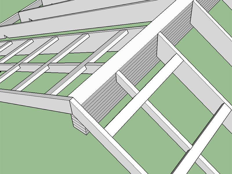
I've added an extra input for the beam which allows ones to specify the overhang of the beam from the outside of the wall. With zero overhang the beam will be flush with the wall framing and not exposed. If the beam overhang is less than the gable overhang, the fly will be as shown below (up to the roof peak). If the beam overhang is greater than the gable overhang it will project past and the fly will adjust accordingly. The beam overhang is not restricted in any manner.
-
I remember a few years back when I was in college and working a side job as a construction laborer we framed up a roof similar to this. The rafters were large I-Joists (TJI 560 equiv.) and were hangered from the glulam beam. The beam was probably almost 2 feet deep. I just remember I was glad I was cutting the blocking on the miter saw and not the one at the peak of the roof setting the rafters into the hangers.
With that being said I am wondering how often I-Joists are used in this type of application versus common lumber. I can probably add in an option to use them instead of common lumber. One question I have though is what to do at the other end, where they bear at the wall. I would need to study this further.
-
The I-joists are used often here in northern California--I couldn't say HOW often. Not a great deal. I know that on the last project we tried to use them, due to the inability to cut them for various conditions, and the special requirements for bearing, and relative strength, we changed the design to microlams. They are also not as easy in fire rated assemblies.
You are making quite a huge extension! Are various members produced in components for modification afterwards? For example one were to modify all tails. I say this because, obviously you are getting close to realistic representation, but if one is seriously using this to show an actual structures, they will want to add modifications, which occur in every building and can't be put into a plugin.
-
@pbacot said:
You are making quite a huge extension! Are various members produced in components for modification afterwards? For example one were to modify all tails. I say this because, obviously you are getting close to realistic representation, but if one is seriously using this to show an actual structures, they will want to add modifications, which occur in every building and can't be put into a plugin.
Fortunately, someone pointed this out to me fairly early on so I have made it a point to make certain elements components and groups in a sensible fashion.
Common trusses and rafters are always components so that modifying tails etc... can be done quickly and easily. Other items such as fascia, outlookers, sheathing, beams etc... are not components but groups (solids).
Also now that I think about it the outlookers should also be components rather than just groups, added to the "todo" list.
-
Glulam beams in the UK seems to be fairly standardized:
Standard Widths: 90, 115, 140
Depths: 225, 270, 315,360, 405, 450, 495Ply: 45mm
-
All of the pertinent details for I-Joists can be found here:
http://www.woodbywy.com/document/tj-4000/
All have to think about this one. The problem with I-joists is the bevel cuts are more difficult since it requires more operations to model. The outlookers at the gable ends would need to notch around the top flange of the I-joist. A double or single bearing plate is required at the ridge or hangers from the beam, notching at the high end of the roof joist is not allowed. Birdsmouth cut at the low end of the joist is allowed but requires web stiffeners on both sides of the joist.
If I can figure out a good method of making the beveled cuts of complicated profiles that would greatly facilitate things.
Update:
I think if I actually model the I-Joist as three groups, make all the necessary cuts and then union them together I may be able to stick with my simple modeling method points -> face -> pushpull
-
With I-joist roofs don't think I would model in any of the web stiffeners, otherwise the model gets too heavy, same goes for small fasteners and hangers.
I haven't even considered the option yet with the rafters resting on top of the beam (dropped ridge). The I-joist manufacturers do not allow notching at the top end and therefore a beveled bearing plate or strip is required with web stiffeners on both sides of the I-joist. Their detail shows a strap across the tops of the I-joists tying them together across the beam, I'm pretty familiar with this detail from some local jobs I've done recently. However, I'm also wondering about the beveled strip on top of the ridge beam, how is it made, thickness at the butt etc...
With common sawn rafters how would you typically handle a dropped beam? Would you use a beveled strip or would you apply a birdsmouth cut at the ridge? I think I've seen both details but what is the preferred method if there is one.
The problem is I'm not out in the field enough so I never get to see this stuff actually go together very often.
-
When the plugin is loaded in a metric template it will now utilize a web dialog with metric sizes for glulam beams. The menu and glulam beam sizes are currently listed at the following link:
I probably don't list every combination possible or manufactured in each respective country or jurisdiction but hopefully I list the most common sizes. So far I have entered in data for the United Kingdom (Great Britain), South Africa, and Australia (and New Zealand).
I can enter in more countries if provided the data (width, depth, locale name and ply thickness). Now that I have the web dialogs and html files setup it is not a big deal to add more entries.
When the plugin is loaded in inches or feet then the US sizes or AWC NDS tables are loaded. So far I have only found one country that still uses the old units.
-
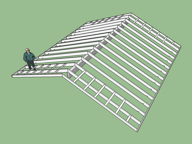
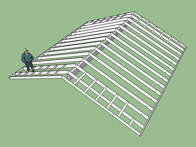
Added dropped beam options for Gable Rafter Roof with Glulam Beam: Notched rafter and Bevelled plate.
-
Version 1.2.0 - 12.13.2015
- Added ceiling joist option for Gable Rafter Roof.
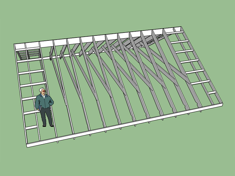
Note: In the image shown I have raised the ceiling joist 24", the default is zero, or resting on the top plate of the wall.
-
With regards to outlookers and I-joist roofs I also noticed in the TJ-4000 (Detail O) they only show the outlookers in a vertical orientation. Are we allowed to do a horizontal orientation (outlookers laid flat)? And if so how do we make that attachment?
-
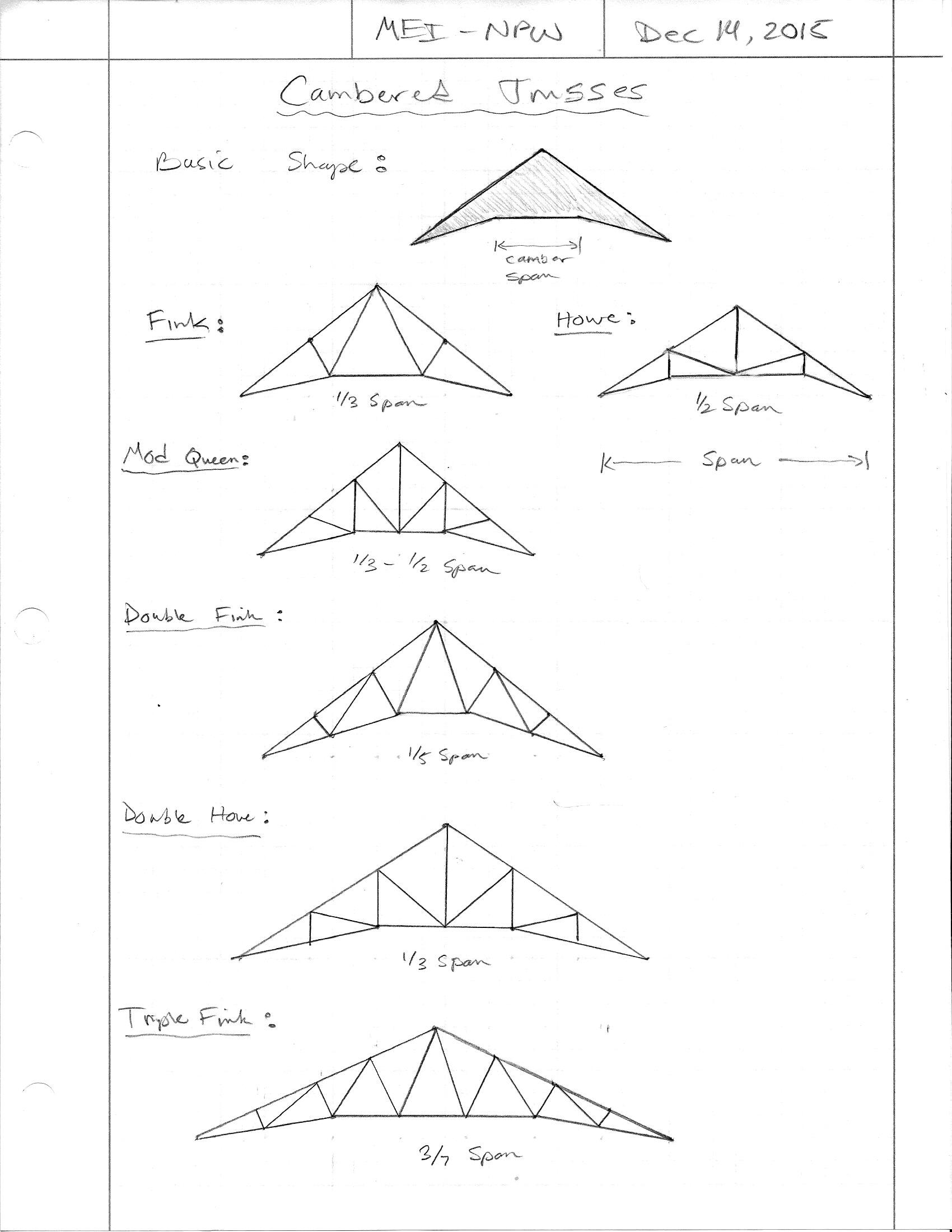
Various configurations of a cambered truss:
-
Things have been a little slow on the plugin development and also on visits to my plugin page the last few days as I have been busy working on some local engineering projects and have not had the time to work on any new features.
Then all of sudden this morning I noticed things were going a little wild on the site with a ton of traffic. Turns out my plugin has somehow found its way to the top of the stack on Extension Warehouse:
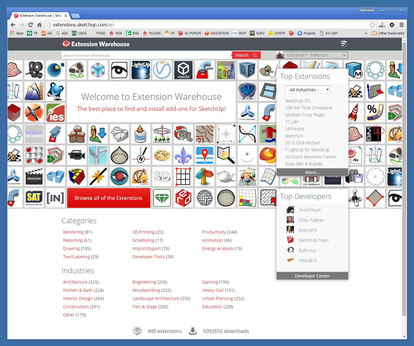
Not sure how it ended up there but my server has registered a serious uptick in traffic.
-
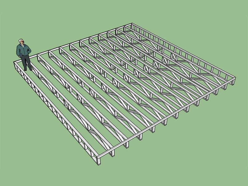
Version 1.2.1- 12.16.2015
- Added gable end trusses (ladders) and ribbon boards to the floor truss type (Warren - System 42).
- Sheathing option enabled under advanced floor options for floor trusses.
-
Version 1.2.2 - 12.21.2015
- Added TJI Rafter Roof with Glulam Beam (all advanced options enabled).
- Added dropped beam option for TJI Rafter Roof with Glulam Beam: Bevelled plate
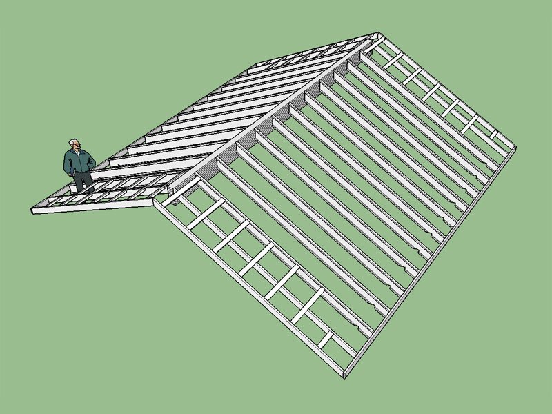
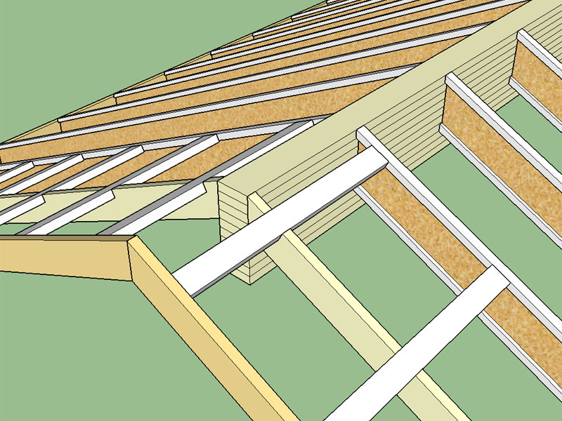
Note, the birdsmouth cut at the lower bearing point. What I am not showing is the additional web blocking (stiffeners) required at this bearing point and at the ridge beam, see TJI-4000 for more details.
-
Version 1.2.2 - 12.23.2015
- Structural outlookers notched around TJI top flange when oriented vertically, as per TJI manufacturer's structural details.
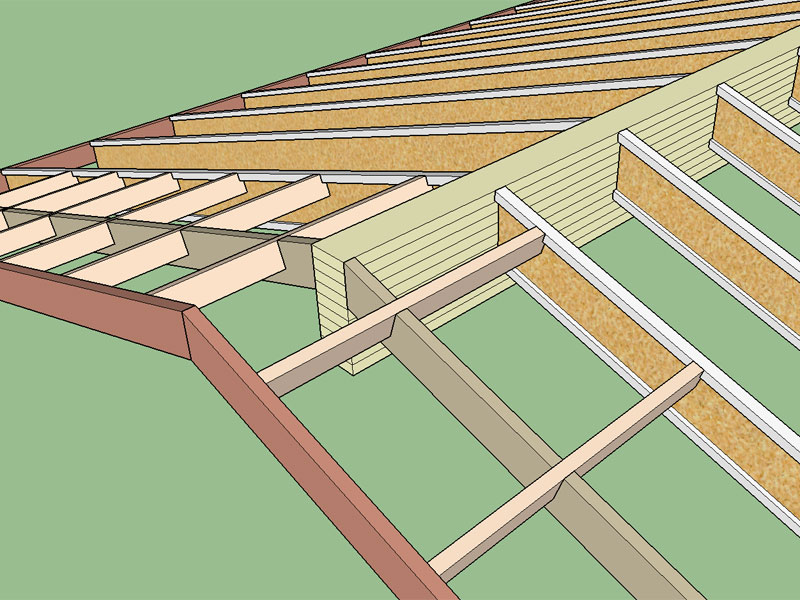
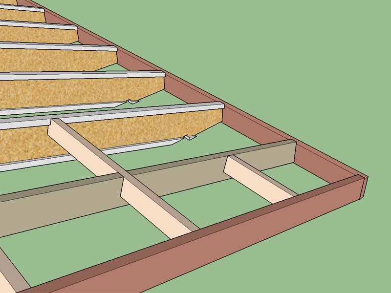
The tails of the TJI joists at the overhangs is left untrimmed however it is very easy to trim the tail of the rafters as shown below to customize to your particular roof requirements.
-
Version 1.2.3 - 12.29.2015
- Added Hip Rafter Roof.
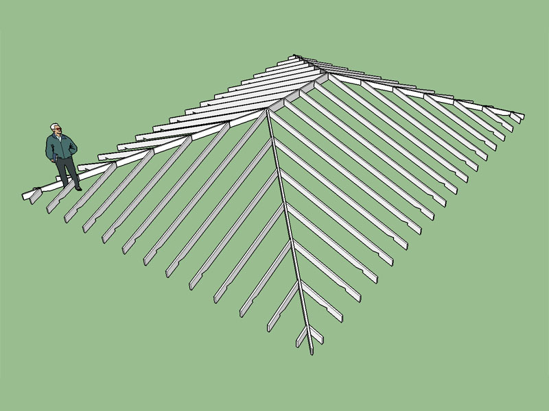
A square hip roof (pyramid):
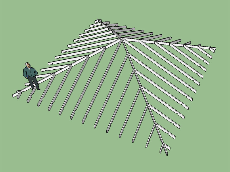
I still need to add in the advanced options for this roof type (sheathing, fascia etc...) I'm also thinking about ceiling joists and how best to configure them. For low pitch hip roofs the ceiling joists near the hip ends will clash with the hip jack rafters unless they are oriented parallel to the jack rafters.
-
A more complex hip roof combined with some trusses. Note I have not trimmed back all of the rafters in the top image.
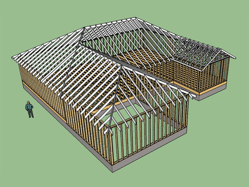
I initially generated the hip roofs (two rectangles) and then deleted the appropriate members and trimmed the common rafters to create the valley jack rafters and cripple jack rafters. The valley rafter was created by copying an instance of one of the hip rafters and moving it into place. The end result is:
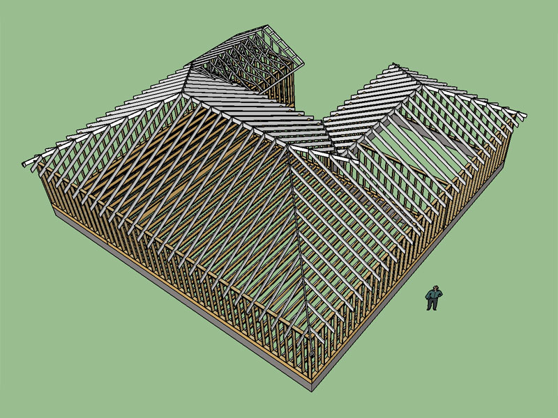
Overall the process has been simplified by having the hip roof feature in the plugin. Trimming the members is the most time consuming, perhaps a more efficient trim tool can be devised so that intersecting members can be easily trimmed back to clean up a complex roof. Ultimately it would be cool to have the plugin automatically handle even more complex roofs such as this but that would take some serious programming.
Also note that I used a raised heel for the trusses so that the heel height and gutter line of the trusses matches that of the rafters.
-
On my Google+ page I posted some recent screenshots of the truss plugin output. One particular individual went on a rather long diatribe on the inferior nature of SketchUp as a design tool, I quote,
@unknownuser said:
"Well, if you are obsessive compulsive, sketchup is your tool. But for people who like to get projects done, there are tools that know what wood is, what lumber is, and know what the construction code is and draw in the meaningless details for you... like framing and rafters.
SketchUp doesn't know what a solid is. Doesn't do edge detection. Doesn't know what physics is. Can't self simply. Doesn't understand physical continuity. Doesn't understand region of focus. Can't deal with camera and material intersection. SketchUp has one intuitive tool, the extrusion tool, and somehow left everything else to confusion."
Some of his arguments I might agree with but it seems like the design community is starting to embrace SketchUp, at least more than I had realized. What made you as a designer or DIY'er decide to use SketchUp versus other design software?
-
Note the cripple or stub ceiling joists in this picture:

Advertisement


