Intersect_with revisited
-
@tig said:
I recommend that 'ents3' should NOT be an 'entities collection'.
Make it a single entity like 'group3' OR an array of entities like 'ents3.to_a'...Its API is very badly written

As you have noticed...Good point! In fact, I believe the method will throw an Argument Error if you try to pass an Entities collection rather than Entities.to_a! But the individual Entities will always be taken to be in model coordinates.
Steve
-
Correcting a misstatement in the first post: the results are transformed using the inverse of trans2 to place them into the destination Entities. That is, trans2 is the transformation that would put ents2 into model coordinates. Its inverse takes points in model coordinates back into ents2. You do not supply the inverse - it is done for you inside intersect_with.
A further wrinkle: if you want to generate the intersections of two ComponentInstances, you can do so as follows:
Suppose ci1 and ci2 are two ComponentInstances you wish to intersect, and that g is a group into whose Entities you want to place the results. Also suppose that these objects are in the same containing context, e.g. directly in the model (more on this below)
e1=ci1.definition.entities
t1 = ci1.transformation

e2_arr = ci2.definition.entities.to_a
t2 = ci2.transformation
invt2 = t2.inverse

et = t1 * invt2
gt = g.transformation * invt2

ints_arr = e1.intersect_with(false, et, g, gt, false, e2_arr)
As noted in my earlier post, intersect_with's calculations always take place in the coordinate system of its final argument, e2_arr - as it must because there is no transformation associated with that argument. Because ci2's Entities belong to its ComponentDefinition, they are in the arbitrary coordinate system of the definition, not in model coordinates. But, concatenating the inverse of ci2's transformation onto ci1's transformation builds a transformation from ci1's coordinates into ci2's coordinates. Likewise for the group g.
You could, of course, transform all of ci2's Entities into the target coordinates yourself, but the way I showed seems cleaner and more efficient to me.
As noted earlier, this snippet assumes that all three DrawingEntities were originally in the same context, e.g. directly in the model rather than nested in another component. The same concept works when they are nested, but you have to build a multi-step transformation to reach the coordinates of ci2 from the coordinates of the other two.
Steve
-
Sigh, I never stop learning...
In fact, you don't have to do the explicit transformation manipulations described in my last post. Just as you can pass a Group as the final argument to intersect_with, so can you pass a ComponentInstance. Both carry a transformation to their context coordinates. As noted, though, all three of the Entities collections need to be from the same context else you will have to build the context-to-context transformations to ents3's context.
Steve
-
I think the topic of
intersect_withis blog post worthy. I'm making a note of it. -
Just wanted to thank slbaumgartner for this pdf. Extremely useful!
-
You are welcome!
Steve
-
In one of my scripts that creates complex parts I had some issues. It appeared that "intersect_with" was behaving inconsisently.
This example uses much simpler parts and therefore you may wonder why I would use a polygon mesh. I wouldn't ordinarily create a door this way. Nevertheless, the purpose is to illustrate what can be done with much more complex parts.
Let's start with a sheet of material which will be machined by CNC. The DXF file is created using a separate process. This is to preserve true arcs as opposed to multi faceted segments. This process is merely for visulization within Sketchup.
Panel Setup:
I will initially create a group (panel) and populate with a portion of the panel using fill_from_mesh. The portion is composed of all the faces that are NOT going to be machined. Then I create the front face and will again use fill_from_mesh. It turns out that fill_from_mesh only works with an empty group. So the solution is to create a second and empty group within the panel group (panel_surface) and to populate it.
Tool Setup:
Now create a number of cutters. Let's go with a 35 mm drill bit and a couple of 8 mm drill bits for construction holes (dowels). Each tool is a component and in 2 groups of 3. Then put the tools into an array (tools).
edges = panel_surface.intersect_with( false,
panel_surface.transformation,
panel_surface,
Geom::Transformation.new,
true,
tools )The problem was some of the intersections were not visible - some of the time. After analysing the edges it turns out that all the geometry was there. So I ended up having to find all faces. Then it worked.
edges.each { |edge| edge.find_faces }
panel_surface.explode

-
@slbaumgartner said:
If you ponder Entities#intersect_with, you will notice a peculiar aspect: there are three Entities collections involved in the operation,
Two Entities collections, and one array of entities.
First is the one you call intersect_with on, the second is there the new entities will appear. The last is the set of entities to intersect with the Entities collection you called intersect_with on.@slbaumgartner said:
All of the examples I found used Groups, and despite having an associated Transformation, the Entities in a Group are actually captured in model coordinates at all times.
Hm... not quite sure what you get at here. But it could be that when you make a group the origin set at the model origin. But if you move the group after creating it the coordinates will be offset. I think this differs from components where the origin is set to the boundingbox minimum.
-
@tt_su said:
@slbaumgartner said:
If you ponder Entities#intersect_with, you will notice a peculiar aspect: there are three Entities collections involved in the operation,
Two Entities collections, and one array of entities.
First is the one you call intersect_with on, the second is there the new entities will appear. The last is the set of entities to intersect with the Entities collection you called intersect_with on.@slbaumgartner said:
All of the examples I found used Groups, and despite having an associated Transformation, the Entities in a Group are actually captured in model coordinates at all times.
Hm... not quite sure what you get at here. But it could be that when you make a group the origin set at the model origin. But if you move the group after creating it the coordinates will be offset. I think this differs from components where the origin is set to the boundingbox minimum.
Both of those early observations were corrected in the more detailed PDF essay later in this topic (which still contains some errors about how the new Edges interact with pre-existing geometry in the destination Entities collection). Ongoing learning and probing...
-
My bad - I didn't look through the whole thread.
-
I wrote up my explorations of this method as the attached essay. Corrections and feedback welcome!
Steve
[Edit: March 2015]
I have since found two errors in the essay.First, the Edges created by #intersect_with will interact with any pre-existing geometry in dest_ents. They may split and be split by pre-existing Edges and Faces in dest_ents. When this happens, new Faces and Edges in dest_ents will result. Again, this happens based on pre-existing content in dest_ents, not based on any interaction with content in ents or with_ents other than the intersection of their Faces.
Second, my description of handling nested Groups and Components is logically correct, but you can't get the required Transformations the way I described. The reason is that for a ComponentInstance or Group that is nested inside another Component or Group, the #parent method returns the ComponentDefinition of the outer Entity, not the specific instance that contains the instance you started with. For Groups this is less of an issue, since each Group's ComponentDefinition has only a single instance. You can access this instance to get the next stage of nesting, and repeat this #parent, #instances[0] sequence to build up the full "path" of Transformations. But for a Component, the ComponentDefinition may have multiple instances, each with a different Transformation, and you need significantly more complicated logic to figure out which one you are trying to use for the intersection. In the SketchUp GUI, you have to open each level of nesting for edit, and the resulting sequence of transformations is accumulated in model#active_path. I don't know of a simple equivalent when you chose the target Entities in Ruby code.
-
My pet peeve with intesect_with is sketchup's random results. In several of my plugins, like FloorGenerator, I create a grid on a face by intersecting a group that defines the grid consisting to faces perpendicular to the "floor" and a group containing the "floor". The "floor" group is then exploded. This works perfectly most of the time but, as faces get more complicated, results can be erratic as illustrated in this screen shot.
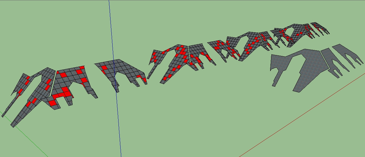 The red faces are faces that consist of two or more grid "cells". Each group was processed with the same plugin using the same grid size with different results.
Anyone else seen this
-
@sdmitch said:
The red faces are faces that consist of two or more grid "cells".
I'm not sure what you mean by this. Do you mean that the intersection produces duplicate Faces?
-
@slbaumgartner said:
@sdmitch said:
The red faces are faces that consist of two or more grid "cells".
I'm not sure what you mean by this. Do you mean that the intersection produces duplicate Faces?
No not duplicate faces but what should be two or more faces somehow combined into one face.
-
What technique are you using to identify the red faces? They look pretty regularly sized, so I am confused about what the floor grid looked like...were its cells of varying size?
I've not seen that effect, but it looks like it is sensitive to the exact geometry involved and its location in model coordinates. Maybe there are "leaks", i.e. Faces not quite closed because of where the intersection points were placed? That could be a consequence of finite computer arithmetic during the intersection. Those look like roof planes, and if so this is probably not the infamous nearby vertices behavior. Maybe you could examine a sample closely to see?
-
@slbaumgartner said:
What technique are you using to identify the red faces? They look pretty regularly sized, so I am confused about what the floor grid looked like...were its cells of varying size?
I've not seen that effect, but it looks like it is sensitive to the exact geometry involved and its location in model coordinates. Maybe there are "leaks", i.e. Faces not quite closed because of where the intersection points were placed? That could be a consequence of finite computer arithmetic during the intersection. Those look like roof planes, and if so this is probably not the infamous nearby vertices behavior. Maybe you could examine a sample closely to see?
I compared the area of the face to what the area of a full "cell" would be and colored red any faces that exceeded the limit. In this case the grid is 1m X 1m.
I would agree that there might be faces not closed if the results was the same each time but, as you can see, that is not the case.
Here is an example of what should be three faces combined into one.
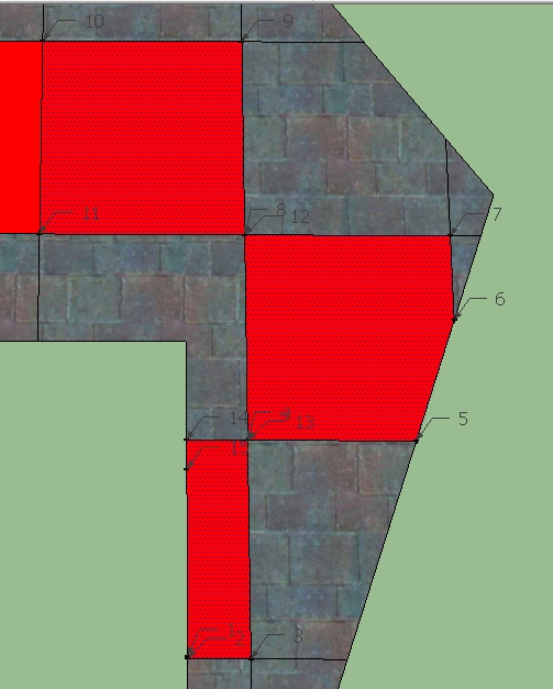
and the coordinates of the vertices- Point3d(3571.39, 1044.32, 154.416), 1. Point3d(3571.39, 1043.97, 154.137), 1. Point3d(3582.77, 1043.97, 154.137), 1. Point3d(3582.77, 1074.56, 178.92), 1. Point3d(3614.04, 1074.56, 178.92), 1. Point3d(3622.14, 1092.34, 193.32), 1. Point3d(3622.14, 1105.15, 203.702), 1. Point3d(3582.77, 1105.15, 203.702), 1. Point3d(3582.77, 1135.75, 228.485), 1. Point3d(3543.4, 1135.75, 228.485), 1. Point3d(3543.4, 1105.15, 203.702), 1. Point3d(3582.77, 1105.15, 203.702), 1. Point3d(3582.77, 1074.56, 178.92), 1. Point3d(3571.39, 1074.56, 178.92), 1. Point3d(3571.39, 1070.32, 175.479)
-
Most intriguing! I don't have an answer, but here's some more discussion for thought...
At least to the precision you printed out, points 4 and 13 are identical, as are points 8 and 12, yet these vertices have not been merged. That is probably the cause of the behavior: the sequence of vertices looks like an ordinary outer loop to SketchUp. But why are they separate? And why did SketchUp gather them into a Face? Possibilities that come to mind:
- they differ in decimal places beyond what you printed but still larger than the merge vertices threshold of 0.001". I don't know what units you used, so can't tell. At full precision, there might be a tiny gap between these points.
- the merge vertices and geometry cleanup operation misfired (which would be a bug!)
- the intersect operation explicitly built these Faces that way (which would also be a bug!)
Regarding the randomness, do you get different results if you undo the operation and then redo it with the identical geometry? If this produces the same results but moving or changing the geometry in any way causes different results, it sounds like a computer arithmetic problem that varies depending on the exact values encountered (not that this observation gives you a clue what to do about it
 .
.One trick I've had work in some situations is to nest everything one extra level deep in a Group, do the work, and then explode that temporary Group when completed. This seems to trigger another round of geometry cleanup which may repair the flaws.
-
If you are likely to get faces with 'twisted vertices', e.g. forming 'bow-ties' or in your case worse...
Then I suggests the following...
Collect the vertices' points into an array.
Get a face normal vector from one of the faces -vec=face.normal
Add a temporary group into those faces' context.
Iterate the collected vertices' points.
For each point, add short 'vertical' edge to thetemp_group.entities...
Collecting the new edges as you go...
Initiallytedges=[]
then iterating...
tedges << ents.add_line(point, point.offset(vec))
When done, explode the group to try and split the 'bow-tie' faces.
Finally erase thetedges- testing for validity...
temp_group.explode tedges.each{|e| e.erase! if e.valid? }
If those faces which need to get fixed are 'coplanar', then there is no risk of the newtedgesgeometry clashing with some existing geometry, so the validity check is academic...

-
@slbaumgartner said:
Most intriguing! I don't have an answer, but here's some more discussion for thought...
At least to the precision you printed out, points 4 and 13 are identical, as are points 8 and 12, yet these vertices have not been merged. That is probably the cause of the behavior: the sequence of vertices looks like an ordinary outer loop to SketchUp. But why are they separate? And why did SketchUp gather them into a Face? Possibilities that come to mind:
- they differ in decimal places beyond what you printed but still larger than the merge vertices threshold of 0.001". I don't know what units you used, so can't tell. At full precision, there might be a tiny gap between these points.
- the merge vertices and geometry cleanup operation misfired (which would be a bug!)
- the intersect operation explicitly built these Faces that way (which would also be a bug!)
Regarding the randomness, do you get different results if you undo the operation and then redo it with the identical geometry? If this produces the same results but moving or changing the geometry in any way causes different results, it sounds like a computer arithmetic problem that varies depending on the exact values encountered (not that this observation gives you a clue what to do about it
.One trick I've had work in some situations is to nest everything one extra level deep in a Group, do the work, and then explode that temporary Group when completed. This seems to trigger another round of geometry cleanup which may repair the flaws.
I have set the precision to the max and that doesn't solve the problem. I have undone and redone with different results. I thought about the multi-level group and created three levels worth that may have lessened but didn't eliminate the problem.
There definitely seems to be a problem somewhere in the way sketchup integrates the edges created by the intersect into the model.
-
@sdmitch said:
Anyone else seen this
Yes, I've encountered this as well and have had some success with the following method. Instead of exploding the intersection edges into the face group with one explosion, the edges are distributed randomly over something like 20 groups, and these are then exploded into the face group. On complex geometry this is both faster and more robust, for some unknown reason.
I've added a small file and a code snippet to illustrate the principle. Select the two groups and run the script.
mod = Sketchup.active_model # Open model
ent = mod.entities # All entities in model
sel = mod.selection # Current selection

gs = sel.grep(Sketchup;;Group)

#find the edge group
eg = gs.select{|g| g.entities.grep(Sketchup;;Face).length == 0}[0]
#find the face group
fg = gs.select{|g| g.entities.grep(Sketchup;;Face).length != 0}[0]

#collect all edges from the edge group
es = eg.entities.grep(Sketchup;;Edge)
#compute a tranformation from the edge group into the face group
tr = eg.transformation * fg.transformation.inverse

#create #no_of_groups empty groups in the face group
no_of_groups = 20
ess = []
(1..no_of_groups).each { |i| ess << fg.entities.add_group }

#add edges more or less randomly to the groups
i = 0
es.each { |e|
  ess[i % no_of_groups].entities.add_line(e.start.position.transform(tr), e.end.position.transform(tr))
  i += 1
}

#explode all groups
ess.each { |g| g.explode }

#delete the edge group
eg.erase!
Hello! It looks like you're interested in this conversation, but you don't have an account yet.
Getting fed up of having to scroll through the same posts each visit? When you register for an account, you'll always come back to exactly where you were before, and choose to be notified of new replies (either via email, or push notification). You'll also be able to save bookmarks and upvote posts to show your appreciation to other community members.
With your input, this post could be even better 💗
Register Login


Advertisement