Aparently not a solid form?
-
I just noticed the reason you can't see a damn thing in maya, as you put it, might be because in the file you posted earlier the calipers are 28m from the origin, so when you open it it is probably tiny and way off to the side somewhere.
Always model close to the global origin.
-
It's likely that the model wound up 28m from the origin due to scaling up to work on tiny geometry and back down again. If you do that using the Scale tool, use the same handle for both scaling up and back down. As I wrote about in an earlier post, I leave the original component where it sits and scale up a copy. Once finished editing the enlarged copy, I get out of edit mode and delete the big one. This leaves the original small component in place near the origin with all of the editing done.
An alternative method of scaling up and back down is via the Tape Measure tool. Measure a known length making sure to click at each end. Type a new, larger length and hit Enter. When you are ready to scale back down, measure the same distance and type the correct distance. Hit Enter. The model will get scaled up and back down maintaining the same position relative to the axes. and origin.
-
I keep getting an error from the IGS viewer and it freezes up but only when I try to open this one file. If I make a simple shape and export it to the viewer it works fine (thanks for that tip
 ).
).
Here is a copy of my .skp file which doesn't seem to want to export properly. I'm at my wits end
The model had been moved back to the planar center several days ago when I was made aware of the scaling mistake I had made.
Any help would be very appreciated.I suspect something has gone wrong with the surface of the main calliper piece as is exhibits strange characteristics when I try to alter it in any way.
I tried making engraved (extruded) lines on the surface but this just caused a whole mess of errors that when auto-corrected always resulted in the top surface being deleted and the ends of the tiny engraved "ditches" to be deleted as well. Very strange. The simple pattern I've now successfully placed on the surface was very tedious. The lines kept drawing not directly on the surface so that I had to draw almost all of them individually. Copying sections of them produced thousands of tiny mistakes in the solid inspector.
Thanks for any help.
-
Please, post the model in V8.
-
-
I wonder if the scaling has caused you some issues. The definitions of the components are at different scales. In your V13 as I downloaded it, the main bar component measures 17800mm long overall. It is scaled up from the original size. Component #2 is also scaled up from its original size. Their component definitions were created when those components were correctly sized. The other four component definitions were created at this scaled up size. Perhaps the IGS file shows the components at their definition-defined sizes?
The fix at this stage would be to correct the scale of the entire model--scale back down to life size--then explode the four components that need their definitions corrected and make new components of them.
This scale thing is another reason I use the process I've described when working on small components. It avoids this problem altogether.
-
Thank you all very much for all your help! I've manged to create a file that I can export and use and am now with a very much altered design in the prototyping stage.
This thread can be closed now. -
hi, can u guys check my model, mine also does not contain solid elements, it said something wrong with the surface border, hope anyone could repair it for me
-
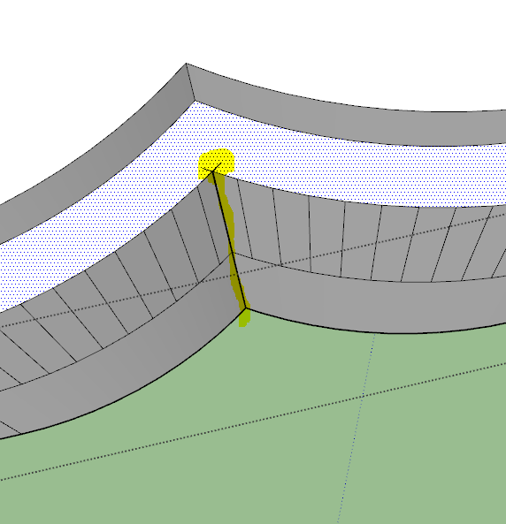
You have some convoluted intersecting edges/faces at one internal corner.
I found that deleting the geometry relating to it and the two 'spikes', then adding one new edge back in made it a solid...
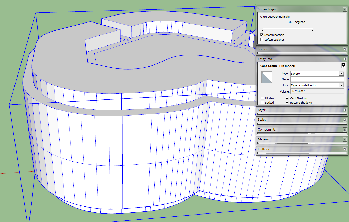
It's easier if you use Monochrome mode and un-smooth all of the edges...
-
thanks man, thanks for the monochrome tips too
Hello! It looks like you're interested in this conversation, but you don't have an account yet.
Getting fed up of having to scroll through the same posts each visit? When you register for an account, you'll always come back to exactly where you were before, and choose to be notified of new replies (either via email, or push notification). You'll also be able to save bookmarks and upvote posts to show your appreciation to other community members.
With your input, this post could be even better 💗
Register Login


Advertisement