Re: [Plugin] Quick Lathe v1.2.0 31mar2013
-
Been working on lots of round things lately, and found myself getting annoyed with "follow me", and the other similar plugins I have - mostly because they always destroy the arcs and curves that I'm following around, which makes later editing fiddly.
So here's my first attempt a writing something that "turns" forms in what I think is a slightly more user friendly way...
v1.2.0 31mar2013
Draft User Guide
The main advantages are...- No need to construct a circle to follow - you just need an axis line.
- Multiple faces can be lathed in one pass.
- The arcs/circles of the lathe paths remain intact, for easy editing using the 'cardinal points' etc.
- No nasty 'follow me' end points when you only lathe an arc.
- Re-orients inside out solids (only for "capped" solid forms so far - needs work).
- Makes groups or components with lathe axis alignment (axis -> Z)
- Doesn't destroy the original profile geometry (unless you want it to)
- Automatic sub-division into an array of symmetrical component instances
- Choice of end-capped or open forms for arcs.
- Perpendicular terminated arcs option.
To Install... - Download the .rbz file.
- Open Sketchup.
- 'Plugins' menu -> Install -> RBZ Package, and navigate to the file.
- Confirm the popup box.
To use... - Too much to include here any more - see the .pdf download (this will be improved, just a draft at the moment).
Version History.
V1.0.1 - 24mar2013. Fixed a bug where the lathed form moved from the profile position if the profile was not in contact with the axis line.
V1.1.0 - 29mar2013. Component creation, end cap options added. Code re-factoring.
v1.1.1 - 29mar2013. Re-versioned as v1.1.0 was the wrong file with some de-bugging code still in place.
v1.2.0 - 31mar2013 Negative angles and non-coplanar faces now handled correctly. Improvements to 'front-face' correction.
Licence
Free to use, copy, distribute or modify so long as the author attribution remains in the code.
No warranty! - I've tested everything I can think of on my system, but I can't guarantee that it will behave for you - let me know if you think it's doing anything it shouldn't, and I'll do my best to get any bugs fixed.Hope you find it useful.
Trog. -
Very cool! thank you. I like that it leaves the "hoops" welded and straightens out the ends. That'll make it a lot of things faster.
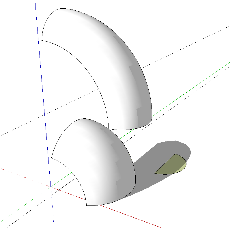
One thing I find curious is that the lathed shapes can get moved from the original location of the profile. The upper shape was turned from the profile shown in green. The plugin put it up above the other lathed shape. Both line up with the near end of the line.

-
Oops

Thanks for spotting that so quick and getting back to me.
Version 1.0.1 is now in the top post - hopefully with my X's, Y's, and Z's calculated properly this time! -
Cool indeed. Thanks.

-
Thank you very much.

-
Steve,
That seems to have dine it. Thank you.
-
Thanks everyone, glad to hear you're liking it!

-
Steve, now the requests are going to start.

Any chance of getting the plugin to create components instead of or in addition to groups? That would be even better for my work flow.
Edit to add:

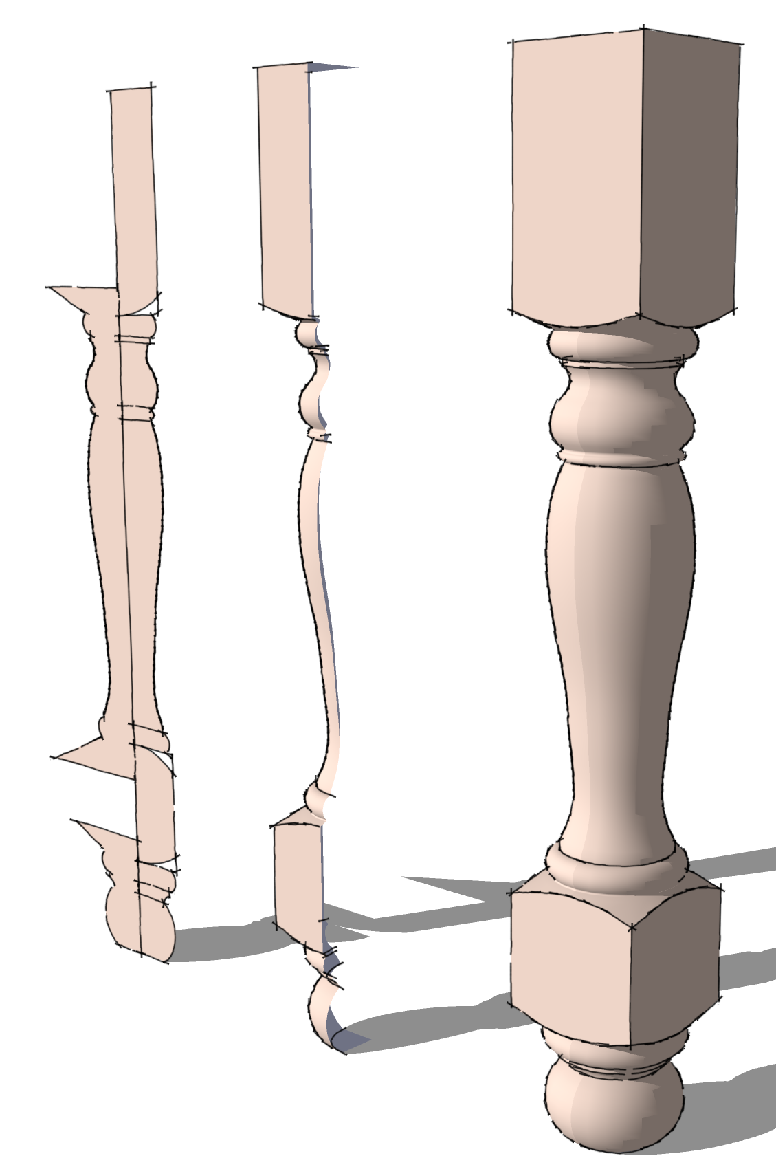
One of the ways I would use this is to replace Follow Me for this sort of thing. For complex turned parts I like to quarter them. It results in less geometry to deal with when drawing and cleaning up around the pommels and it helps to keep file size lower. I make a component of the quarter and save it for future use. Sometimes I want just half a leg or a 3/4 leg for a kitchen island and they are easily made from these quarters.
-
@dave r said:
Steve, now the requests are going to start.
He he, yes, I've seen the outrageous way you all treat TIG, ThomThom, Dan etc., you greedy blighters!


@dave r said:
create components instead of or in addition to groups?
Actually, I already had just that feature in mind - I work on a lot of mock-ups of control panels etc. so this is to be part of my little toolkit for designing knobs and dials.
In fact, it's partly where that bug came from - trying to get the group axis/origin located consistently so that the components could also glue to a face.
I'm just working on a little addition at the moment that gives a clear indication which way the axis line is pointing, and the option to reverse the direction. I usually use the 'trim template from a rectangle' method to make profiles, and it's 50/50 whether the component ends up upside down when you choose an existing edge - which rather spoils the effect! -
Very good plug. Thank you.
-
Nice plugin and thanks for your work.
Noticed, since coplanar faces are not removed or even given an option to remove coplanar faces, after lathing, you can not push/pull what should be a face, i.e. the end of a pipe.
I found this out be doing a lath, that should have made a section of piping. However, when I wished to make the pipe longer, I couldn't push/pull the ends.
Again thank you for your time and effort.
Ken
-
Love it, Multiple on same axis excellent, nice clean and simple to use.
But
Perhaps I have misunderstood this bit@unknownuser said:
- The arcs/circles of the lathe paths remain intact, for easy editing using the 'cardinal points' etc.
It was the main reason for me testing, so sick of recurving/welding etc
But my rings seem to be exploding.
As you can see from the pushpulls in the pic.
It also seem that if I recurve or weld the the ends of the extrusion, it will still break up when PPed. If I copy the profile away from the extrusion it retains the weld. -
Wow, so much interest, I am very flattered.
@Dave - ah yes, didn't see your pic's before. That's just what I had in mind when getting rid of the follow-me "end mess". Might be an idea also to have an option to remove the "end planes" of the extrusion too, as they would just become useless internal faces when duplicating the segments.
@Ken - definitely add that to the 'to do' list For my own intended application I left the 'facets' on co-planar faces as I often want to modify the face later - but I can see how that would not be expected for other applications.
@Box - interesting; again I think probably a case of me being a little blinkered by my own intended use (kind of more like Dave's wood turning examples). The circles/arcs that go around the lathe axis stay 'welded', which was my intention, but I hadn't considered the case of the initial 'profile' face being an arc or curve.
I'll look into that - getting the loops to stay in one piece proved to be rather tricky, so it may depend on how SU handles having welded curves that cross over each other -
Ah I see now.
Would never have thought it was in that direction.
Perhaps a choice of one way or the other is possible. -
Steve, if you are going to modify the plugin for those quarters as I showed, may I suggest that you also see if you can work in a way to get the first and last segments in the extrusion to be perpendicular to the ends of the extrusion? Here's an example where I've set that up for a turned leg. The segments marked in red are perpendicular to each other. These would be the first and last segments for a quartered lathed shape.
I normally set up these types of things that way so I can avoid the shadow line at the seam as you can see in my example in my other post.
As to getting rid of the profile faces, that would be a nice option although it isn't difficult to do manually. Of course for something like my table leg or your knobs, those faces aren't required. the main reason I remove the faces is so it won't show through at the seam lines.
-
You made a very good one here, be proud of you.
Many thanks.
-
@gilles said:
You made a very good one here, be proud of you.
Thankyou Gilles, it's been very satisfying to make something useful - and of course, we must not forget all the other kind and generous people here who made it possible for me to learn all these things.
@box said:
Perhaps a choice of one way or the other is possible
Yes, it looks like it will have to be done that way - I made a little test rig to try putting the welded curves the other way, and bar a few minor bugs, that works OK. But whatever I do, SU won't let there be welded curves in both directions at once - I tried it using some of the other welding and recurving plugins, and it seems that the geometry just isn't allowed to work that way.
So it will have to be an either/or thing.@dave r said:
first and last segments in the extrusion to be perpendicular to the ends of the extrusion
Hmm, i hadn't considered that, but i know what you mean, it does kind of spoil the appearance when you get those unsmoothed joins.
I'll have tinker and see how likely it is once I've tidied up a few other things - the code is getting a little unmanageable with all this "feature creep" going on, so I need to get everything nice and structured so I can see the wood for the trees.PS) Just about there with the co-planar faces thing, so maybe a minor update coming soon just to get the low hanging fruit picked off.
-
Version 1.1.0 now available in the Top Post.
New features...
- Co-planar faces can now be merged.
- When doing arcs, you can choose capped or uncapped ends (or hidden ends for 'seamless' component arrays)
- Can now make components as well as groups.
- New features added for making arrayed component 'segments' which will join seamlessly, including perpendicular end-caps (as per Dave R's examples in above posts).
- First draft of .pdf user guide (very rough - needs many pictures adding!!)
- Re-factored code should be a little faster and more robust (and maintainable!!)
Still to do...
- Face orientation correction only works 100% for closed solids ("capped" arcs and 360deg lathes). Sure this is fixable.
- Extrudable end caps - losing co-planar edges makes push/pull possible now, but still working on making them 'smooth aware' for when circles and arcs are extruded.
-
Ooops' apologies to whoever just uploaded - that wasn't the right Ruby file. Re-upped!
-
Just select the face WITHOUT its edges and a line for axis.
Works fine.
Advertisement


