Barley Twist Spirals
-
Good point, Peter.
When I draw pommels and such I tend to make them much larger in diameter than needed and trim them back. I tend to think of it a bit in terms of turning in wood by hand. The cutter would run along the pommel shape and off the wood in a smooth continuous action and not stop right at the edge of the wood. You can see a similar sort of thing in this octagonal pedestal.
-
It looks a bit like the bowl is not big enough in circumference. It can be larger so that it's rim is beyond any intersection with the twist. You are just going to delete the extra anyway. Same with the twist. At the bottom it looks like it isn't long enough to be sticking out of the bowl. Overlap them completely.
EDIT, Here's my try. I find in using screw.rb (did you?) It's easier to use the same number of segments for other forms that join to it. It helps line up the geometry. IDK the proper termination, but mine looks like it needs some sanding. I think the bell shape might need be as tangent to the spiral shape as possible. which leads to the very problem. You also need a good intersection!
You can see the geometry line up in the second picture
The third picture shows an attempt to "sand it down" with Artisan. Get out the 100 grit!
More turnings (slow processing) may give better results. Also, I did not bother to adjust the segments in my profile arcs. Probably should not be such a large variance in spacing.EDIT: More notes: the two shapes are separate groups. Enter each and intersect with model. You can dbl. click the excess face and delete. I find it helps sometimes to leave the excess in place until done with both intersect-with-model operations. Seems SU does not always recognize a one edge intersection.
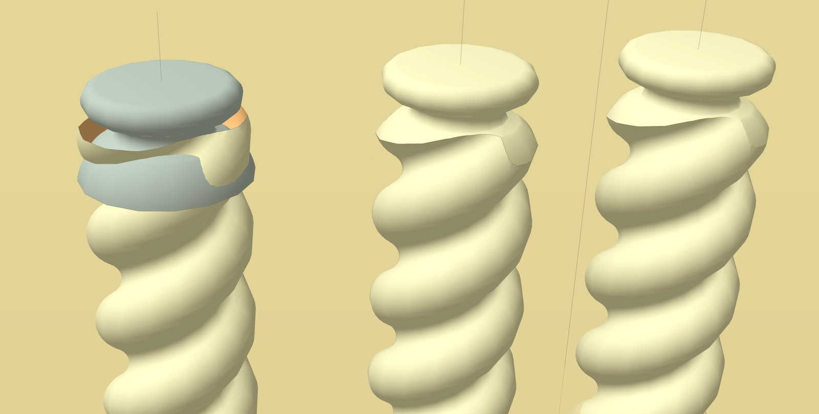
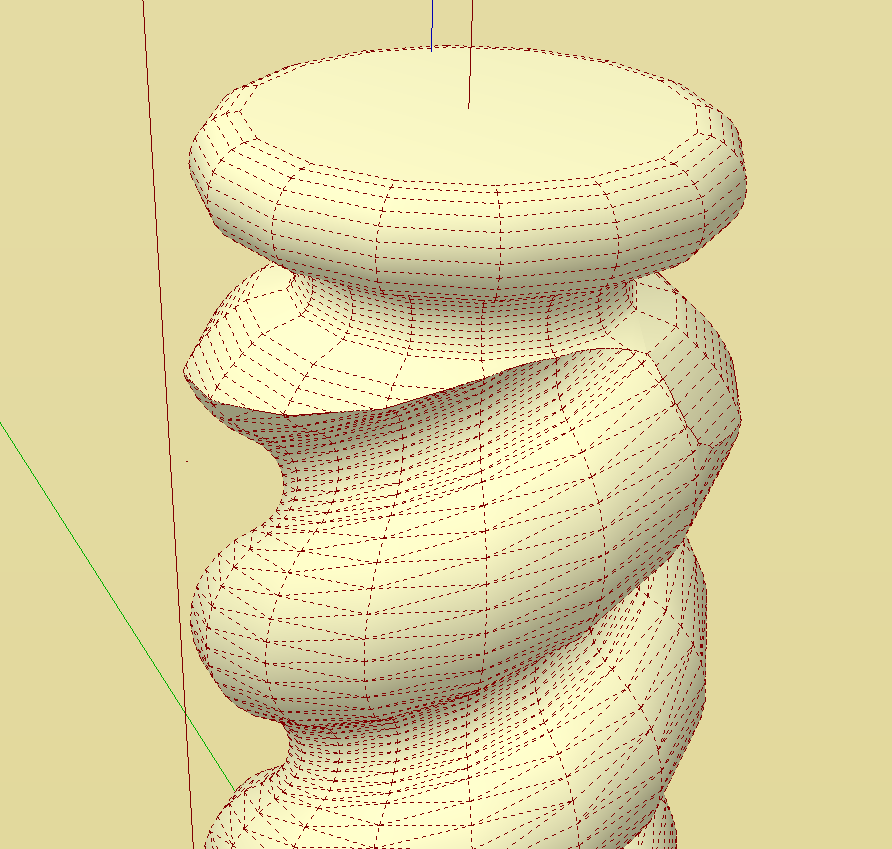
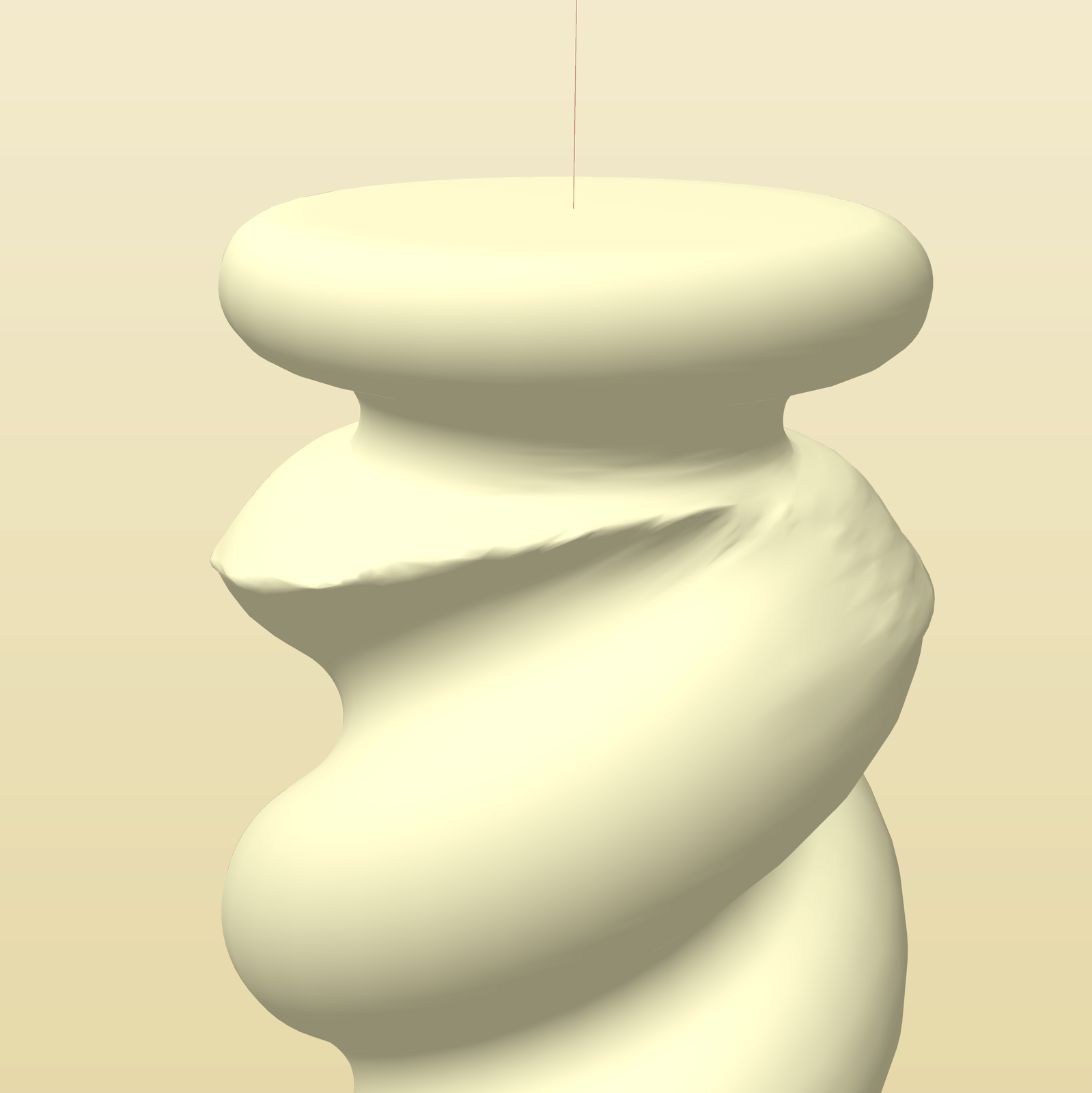
-
It definitely helps to resize. I noticed when using the Zorro plugin I got jagged edges. So resizing is a plus. However I am still missing something. I understand that I have to be in edit mode of my group to make then intersection. But does the other object have to be selected as well? That would mean that the second object would have to be part of the edited object?
Also I'm wondering why I get a nice surface for my barley twist but portions of my tuning are lines?
I would upload my SU file but it is too large to upload.
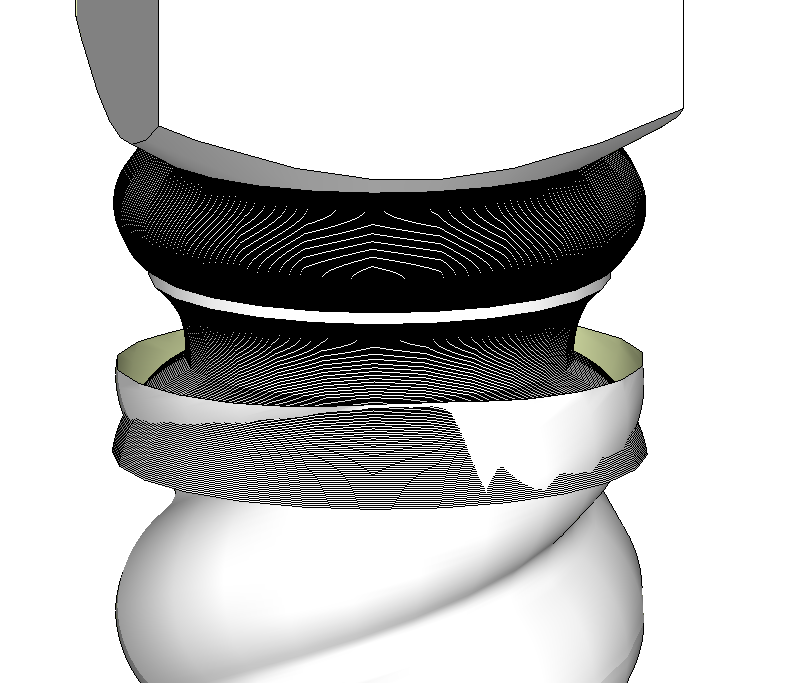
-
Although you could make an intersection between the twist geometry and the other part of the turning with the other part outside the component (or group), You won't get the faces you need. So the other part of the turning should be in the same context, i.e. inside the component (or group) as the twist geometry.
The jagged edges are due to the intersection of two faceted surfaces and really can't be entirely eliminated. You can minimize them by having the same number of edges in both curves but that'll be difficult to manage in this case. If you were making the twist with each start a copy of a component, you would have an easier time with the intersection and less to deal with.
I'm not understanding why you are using Zorro for any of this.
The lines you're seeing are due to unsoftened geomtry. I don't know if it is something you are doing that results in the unsoftening or if you are doing something with a plugin that causes it. You can fix it by selecting the area, right clicking and choose Soften/Smooth. Or is it Smooth/Soften?
-
@pbacot said:
EDIT, Here's my try. I find in using screw.rb (did you?) It's easier to use the same number of segments for other forms that join to it. It helps line up the geometry. IDK the proper termination, but mine looks like it needs some sanding. I think the bell shape might need be as tangent to the spiral shape as possible. which leads to the very problem. You also need a good intersection!
You can see the geometry line up in the second pictureAs far as I know I am using the same number of segments. SU uses 24 by default and I am setting up the screw dialog to 24
@pbacot said:
EDIT: More notes: the two shapes are separate groups. Enter each and intersect with model. You can dbl. click the excess face and delete. I find it helps sometimes to leave the excess in place until done with both intersect-with-model operations. Seems SU does not always recognize a one edge intersection.
Do you mean here to "Select" each and intersect with the model?
So you are selectimng both twice and intersecting? -
In response to Archturn (last post): Select each group (or component), the spiral and the cap, separately. Open (edit) each group and perform intersect with model. This way you can check the intersection is correct and easily delete unwanted material in each. You may want to hold off deleting, until after you've performed both intersection operations. Then you have two groups. You can join the geometry together when you are ready, but I feel you have more control this way while working on it.
Dave: "So the other part of the turning should be in the same context, i.e. inside the component (or group) as the twist geometry."
I don't think so. If you leave these as separate groups you can perform intersect "with model" from INSIDE each group. IMO you have an easier time then selecting parts to delete and checking the joint before committing to joining the geometry up in the same context.
check with hidden geometry that the vertical sections of geometry align. But either way works. That's just my preference.Can you just upload the parts in question? zip it?
-
Peter, yes, you can get the intersect but there'll be no faces created, in this case, to terminate the twist geometry.
Take a look at the example.
In the foreground there are two components. I opened the cylinder for editing and performed Intersect Faces>With Model. The faces were intersected and edges were created at the intersection but notice there are no faces in the resulting notch.
In the background, the box is in the same context as the cylinder. After intersection and deleting the waste, there are faces created in the notch.
-
@dave r said:
Although you could make an intersection between the twist geometry and the other part of the turning with the other part outside the component (or group), You won't get the faces you need. So the other part of the turning should be in the same context, i.e. inside the component (or group) as the twist geometry.
Ok Got this part
@dave r said:
The jagged edges are due to the intersection of two faceted surfaces and really can't be entirely eliminated. You can minimize them by having the same number of edges in both curves but that'll be difficult to manage in this case. If you were making the twist with each start a copy of a component, you would have an easier time with the intersection and less to deal with.
Dave
I think I do have the same number of edges - 24. Will try as you said with each twist a copy of a component@dave r said:
I'm not understanding why you are using Zorro for any of this.
Just to make it a bit easier to mange at the intersecting point
@dave r said:
The lines you're seeing are due to unsoftened geomtry. I don't know if it is something you are doing that results in the unsoftening or if you are doing something with a plugin that causes it. You can fix it by selecting the area, right clicking and choose Soften/Smooth. Or is it Smooth/Soften?
Dave I tried the soften geometry to no avail. I've included a file with a sample part.
-
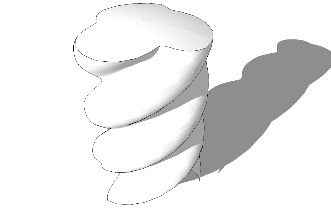
Crossing posts but here's an example of the round end applied to the twist. Obviously I didn't bother with anything above the termination of the barley twist but there rest is pretty simple. This was done with the twist and a shallow dome in the same context.
I'll take a look at your file as soon as I get a minute.
-
It worked for me. I selected all of the geometry, right clicked, chose Softe/Smooth Edges. I also corrected the face orientation.
In my opinion you're using way more segments for your curves than are really needed. This will increase the likelihood of running into the tiny face issue. I think you could reduce that quite a lot without having any real noticeable loss of detail.
-
@dave r said:
It worked for me. I selected all of the geometry, right clicked, chose Softe/Smooth Edges. I also corrected the face orientation.
Wow
Doesn't work for me. Can SU get tired?
-
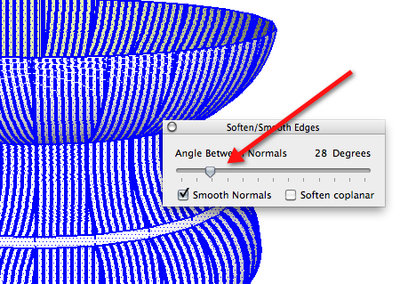
I don't know. I've never worked it that hard. Did you try moving the slider a little?
-
@dave r said:
I don't know. I've never worked it that hard. Did you try moving the slider a little?
Slider??
-
-
check this, and Dave is right, you don't need so much segments in your vertical curves.
You must consider the purpose of creating the model:make a render
creating shape for produtcs
create a catalog of your products for architects....Stay low poly as far as you can, go see to the gallery and you will see impressives models with low poly.
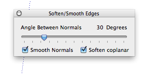
ho ho cross post

-
That did it
Thanks -
@dave r said:
Peter, yes, you can get the intersect but there'll be no faces created, in this case, to terminate the twist geometry.
Take a look at the example.
In the foreground there are two components. I opened the cylinder for editing and performed Intersect Faces>With Model. The faces were intersected and edges were created at the intersection but notice there are no faces in the resulting notch.
In the background, the box is in the same context as the cylinder. After intersection and deleting the waste, there are faces created in the notch.
That's clear Dave. But in this case the faces we want are already formed. By the intersection performed, we don't want faces formed, we just want to create cut along the intersection. Worked fine as in my example.
-
Ta Daaaaaa
I want to say a big thank you to all that helped. I think I finally got it. As it turned out the intersecting was the most difficult for me to get. With the screw plugin there is really not much to it doing the barley twist.
I hadn't learned about resizing to get larger faces before - big plus there. I had to read and re-read Dave and Peter and Gilles post to finally get the intersection part. Thanks all!!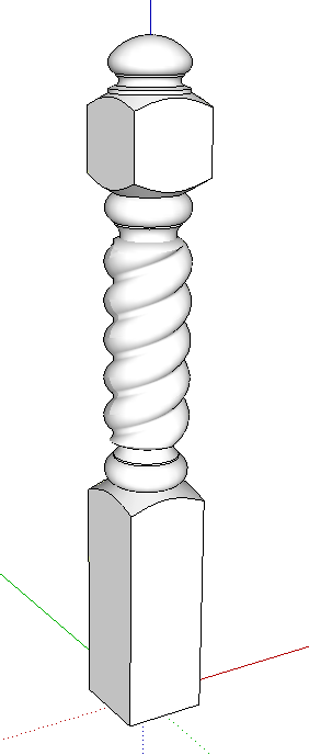
-
Hey! That turned out nice. Good work.
-
Yeah, that's a nice one! Thanks for starting this thread too!
Advertisement


