Component insertion point problem
-
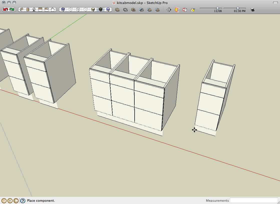
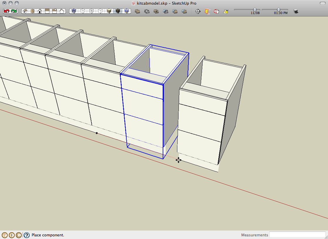
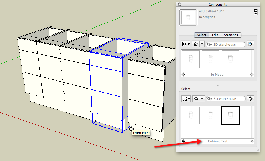
OK. Component files and a model with components inserted attached. The 300 and 350 wide units seem to insert ok but the 400 'jumps staight in' at the origin.
Thanks
-
There is a very long write up in the user manual on this subject you should read.
Here is a note I copied from it.
"Note: The component axes is the default insertion point (the point where the cursor grabs the component) for a component the first time you place the
component in the model from the Components browser. The insertion point will change to the point where the Move tool selects a component if you place
a component and then reposition the component using the Move tool."
BTW here is the guide http://commondatastorage.googleapis.com/support-kms-prod/SNP_2668174_en_v0 -
I'm not having any trouble with any of them.


-
Dave R, have you tried putting the components into a file in the components directory and then loading it from their or are you loading them from the 'in model' list?
I have just got home and tried it on my PC and I am now having the same problem with all of them. -
Mac1, sorry didn't see your reply earlier Yes I have read the manual and what is described there is not happening for me. The cursor is not changing to the move tool when I select from the component library.
-
Yes. It works fine that way, too.

-
OK thanks. Still not working for me. Don't suppose its 'cos your on a Mac
-
I can try it on my PC when I get home from work although I don't expect anything different.
You're dragging the components in by clicking on their thumbnails in the Components browser?
-
You're probably right. Yes I am dragging them in from the thumbnail, or at least trying to. They just snap to the origin. May have to start from scratch, I have made about 30 of them based on the same component exploded, resized and reformed into the next size up unit. Must be something wrong with the first one so all others are affected. Doesn't seem to relate to the Geo location issue mentioned in other posts either.
-
Strange.
Why are you exploding, modifying and making new components? That seems like the hard way but maybe you like the extra work. If I was doing that (and I have in the past) I would simply make a copy of the component, make the copy unique, modify it as needed and give it a new name. I'd have the component's origin and axes set on the first one and make my modifications on the new ones so that the existing axes are always in the right place.
Models such as kitchen cabinets shouldn't be geo-located at all.
-
Thanks Dave. Hadn't thought of your method for modifying/making components, does sound easier. Guess I'm not as 'intermediate' a user as I thought. I haven't geo-located the units
but saw it mentioned in other posts as a potential issue.
Mac1, thanks for giving it a go. Not sure what you mean by the 'mirror approach' though.
Will try it all again tomorrow when I'm back at work. -
PC here + SU free M2 and cannot duplicate your problem. The only way I can get unit to jump to origin if I use the "replace selected " functionally of the component browser. The insertion point works like the user manual. IE if I bring the 400 unit in from the browser, then use the move tool to move to origin by using a mid point then the next import from the componet browser uses the mid point and not the the componet axis as the insertion point. It is noted the base cabinet does have a gluing plane set and noted something strange to me because when I double click an axis was showing out side the bounding box. I guess this was because you are using the mirror approach to create it. Exploding and making a " regular" componet removed this but don't think it is part of your problem.
Not dragging in from thumbnail but by select in the browser list
And when doing that I do get the move tool" cross" when dragging to insert. Does this mean a different version artifact?? or a graphics card issue?? or ??
Sorry missed part of your post. I am using the models from the in model list included in your zip file. -
Don't bother spurious comment. I thought you may have modeled the base 1/2 and created the total by mirroring that 1/2 but axis was coming from the side panel solid group. You are keeping the dimension consistent as far as the 18 mm panel width but did notice the 400 model was measuring 450mm width at back.
-
 That means I labelled the model incorrectly after resizing it
 -
Nickchun:
More comments:
1)The 400mm model stand alone skp file in your zip is a different size that the one in the kitcab file model;
2) If I open the 400 stand alone model it opens at the expected drawing axis origin, importing the 300 and 350m then into the same drawing will then come in as components even though they are not componets in the zip fileoffset some what and with out the move tool;
3) SU treats components differently for ones created within the specific skp file. Try scaling one with the tape tool and you will see that.
I am coming to the conclusion what are you seeing is just an artifact of the work flow you have going. Especially since both Dave R and I am found no problem when opening from the kitcab file. Have you tried opening from the in model component browser and found same problem?
4) If all your cabinets are separate files suggest you create a collection or library and try again and see if the problem is still there.
Advertisement


