Newbie Sayin' hi ....
-
Hi folks,
My name is Tim.
My interest in SketchUp originated from my Woodturning hobby, later when I get more familiar with the forum I'll try to post an example of what I'm learning to do.
I'll be on the look out for tutorials and discussion regarding simulated wood lathe designs and SketchUp techniques that apply.
Thanks,
Tim -
Hi Tim and welcome,
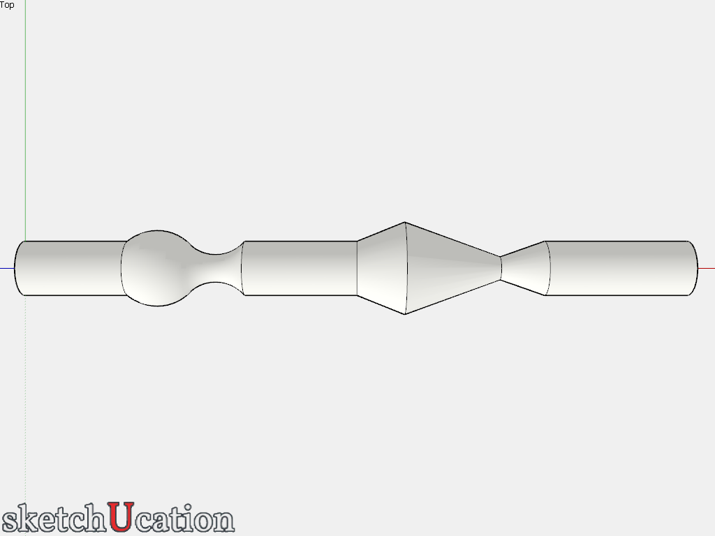
My native language is not English. Would something like this be called "woodturning"?
-
@gaieus said:
Hi Tim and welcome,
My native language is not English. Would something like this be called "woodturning"?
Good Morning Gaieus,
It is in fact, what you've shown is called spindle turning. Typically spindle turning is used for chair and table legs.
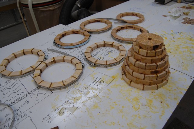
I specifically enjoy making "Segmented Bowls" this involves a process of cutting wood into specific sizes segments which when glued together form a ring, the rings are stacked and glued together which roughly forms the bowl or vessel being built. The final shaping and finishing are done on the lathe.
This link http://www.finewoodworking.com/item/22170/sketchup-and-the-lathe
suggests what I want to become proficient at, however, as an absolute beginner with SketchUp I haven't yet been able to follow the steps and design a project.Here is a pic that shows some assembled rings being stacked into a bowl shape.[img][img][img][/img][/img][/img]
Thanks in advance for any and all help offered,
Tim
-
Okay, I see. These segmented things are extremely easy to make in sketchup since every currve is actually made up of segments. So what many people hate in SU (being a surface modeller, just approximating curves), you will definitely enjoy.
-
Dave's example is how to replicate a woodturning process to make a bowl using a 'lathe' operation with profile-face and a path from a circle, with the followme tool.
Making a segmented bowl is similar but requires a different process.
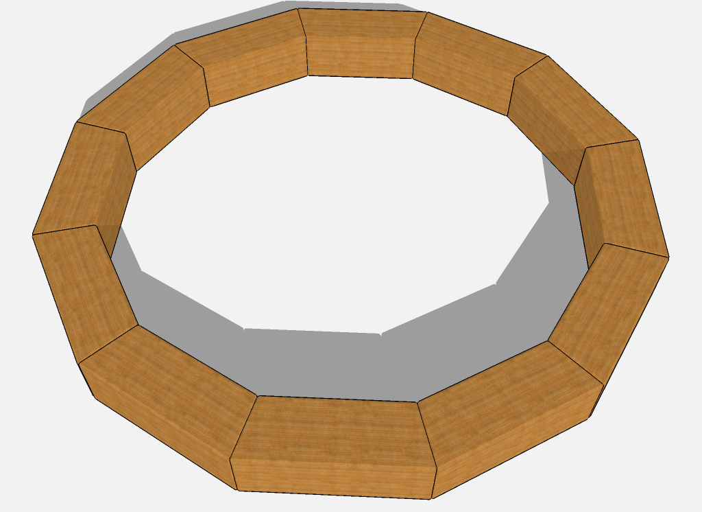
First off decide how many segments there'll be a circle - let's say you decide on 12 [like the image] - so that's 360/12 = 30 degrees for each 'wedge'.I suggest you first make a "circle-template" to help you.
Draw a flat circle centered at the origin, say 12" radius [type that in], also type 12s so it has 12 sides before committing it.
Draw a diameter line between two segment vertices - say along the red axis.
Select the line and activate the Rotate tool.
Hold the Ctrl key to enter 'Copy' mode.
Pick its pivot point as the origin [line's midpoint].
Pick a point on the circle and move the copy approximately and type 30 + <enter>, it's now 30 degrees rotated around the circle, immediately type in 11x + <enter> to make all of the needed copies.
You now have a fan of 30 degree wedges
Draw some other circles using the same center at say 1" increment radiused within the main shape to make a 'spiderweb'.
Select it all and make a component of it - choose its insertion point/axes as the origin.
Now other things won't stick to it.At this point you should make a "cross-section-profile" - that is a vertical face aligned along the red axis [made into a component] - say 6" sq with the curved outline of half of a bowl drawn on it, add vertical lines every 1" too. Locate it on the red axis it's a useful guide for wedge sizing etc...
You can use this to set out your wedge-shaped segments.
Draw over the four sides of a desired wedge on the outer rim of the bowl [adjacent to the red-axis] and a face forms.
Use pushpull on it to make a 3d shape - say 1" high.
Treble-click to select all of the geometry and make a component of it - name it so you can find it later - pick its insertion point at the origin for easy reuse.Repeat his method to make another 3d segment-wedge - remember to give it an 'overlap' with the first one, using the "cross-section-profile" verticals/curve as a guide.
I suggest you make the later wedges over the adjacent wedge-sector of the "circle-template" so you can see what you are doing.Once it's made into a component you can rotate it about the origin/center 30 deg back to the common 'sector'.
You can then lift this second wedge up 1" with Move so it's now over the first one [we are modeling this bowl upside down !Repeat for the other wedges, forming a stack of 'segments' as a 'profile' next to the red-axis.
With the "cross-section-profile" adjacent to the staked wedges you can adjust the positions of the various wedges so they still overlap but follow the profile too...
You can then copy the preselected wedges around the center of the "circle-template" using Rotate+Ctrl 1- you need not enter 30 as you can pick two points on the "circle-template" that you know are 30 degrees apart, type 11x to replicate the copies fully around the form.
Now you have a completed bowl of wedges.
I suggest you make a component of them all with its origin centered. That way you can manipulate - e.g. turn it the right way up ! - and color individual wedges etc to make patterns.
When it comes to cutting the wedges in real life you know the angles are all 30 degrees and you just need to measure the 'plan' dimension to ensure the 1" stock is cut to the right size. -
-
WOW ... Thank you very much for the time you've spent to help me here, there is a steep learning curve here for me and I suspect working through your instructions will be a challenge. I'm going to work with it right away and see how I do.
Tim
-
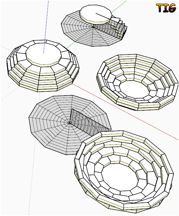
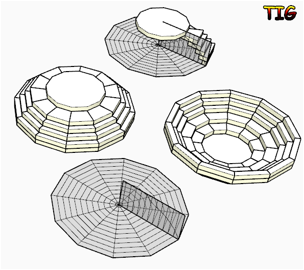
Good luck...
Here is an alternative where alternate rows of wedges are offset by 15 degrees giving a brick-bond effect. This is stronger that the original version shown. To achieve this I simply made a unique copy of the bowl component [context-menu] then edited it, viewed it from the Front with Perspective OFF and used Select with a right>left thin fence passing through alternate rows, +Ctrl [to add to the selection] - then Rotate about the origin and enter 15 to make them 'offset'...
-
@tig said:
Good luck...
Here is an alternative where alternate rows of wedges are offset by 15 degrees giving a brick-bond effect. This is stronger that the original version shown. To achieve this I simply made a unique copy of the bowl component [context-menu] then edited it, viewed it from the Front with Perspective OFF and used Select with a right>left thin fence passing through alternate rows, +Ctrl [to add to the selection] - then Rotate about the origin and enter 15 to make them 'offset'...Good Morning,
The off set row design is typically how such a project is built.
I should have been clear from the beginning, many of the terms and procedures you've so graciously described are so new to me that even attempting to follow step by step directions will be very difficult. Tutorials have been my main source of study and I feel the easiest to learn from.
I'll continue to watch every tutorial I find and practice, practice and practice.
I've saved all the instruction you've written, once I've become better acquainted with the program and it's basic functions I'll be better able to reproduce these procedures.
Thanks again for your time and help.
Tim
-

The brick-bond version with the wedges rotated half-a-turn in alternate rings is indeed quite common, especially with two or more contrasting colored woods used for alternating wedges in a ring, which can give 'spiral' effects etc.
However the 'stacked' version is also sometimes used with wedges that are mainly all of the same wood but with thin slivers or narrower wedges of contrasting colored wood inserted between every wedge in every ring and perhaps even between the rings themselves to produce a 'net' pattern...
There are many permutations - even leaving out wedges to make a 'pierced' surface...Enjoy makin' shavin's...
Hello! It looks like you're interested in this conversation, but you don't have an account yet.
Getting fed up of having to scroll through the same posts each visit? When you register for an account, you'll always come back to exactly where you were before, and choose to be notified of new replies (either via email, or push notification). You'll also be able to save bookmarks and upvote posts to show your appreciation to other community members.
With your input, this post could be even better 💗
Register Login


Advertisement