Dimensioning orthographic views
-
I am exploring the possibility of migrating away from ACAD for my 2d workflow, so I have watched tutorials and have read many many articles on dimensioning in Layout. I have seen many examples of highly detailed construction documents being produced with layout. I know it's possible.
So today:
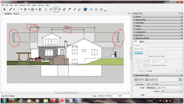
I am trying to dimension an orthographic view of a house elevation in layout 3. When I pick points for the dimensions, Layout is giving me the dimension between the points in 3 dimensional space, not the 2 dimensional orthographic view. For example, at the gable end of the elevation, I want to provide the dimension from the peak of the roof to the eave, Layout is giving me the dimension along the roof slope, not the vertical dimension. When I want a dimension of a dormer ridge, I keep getting the distance from the near peak point to the end of the dormer. This is also a hypotenuse dimension, rather than a 2d dimension.
Is there a setting I am missing? Also, today I updated to SU8pro M4 (if that means anything)
Frustrated but not giving up.
Please Help

-
That's the default way that LayOut works: ask the 3D model for the dimension and report that. However, if you wanna do the old school way of scaling from paper, you can do that, too. Click on the dimension, then (the menu) Window->Dimension Style and set the dimension to NOT auto scale, and select the scale you want.
-b
-
Hey b,
Thanks for the tip. I just tried that same approach. I manually selected the scale (not auto scale) and I am still getting the 3d model info as opposed to "old school" ortho dimensions.
Any other thoughts?
-
The attached file is a screen capture of what I am trying to dimension. I believe I have the settings correct, so what can I try next? BTW this started when a client asked for the dimension from eave to peak along the gable end of the elevation. That particular dim string is not shown in this view, but the issue still remains on how to dimension orthographically.

-
To Sketchup Team,
I may have figured this out by screwing around some more.
Here is what I think is the issue. The drawing that I was dimensioning was from a model that I had rotated about 45 degrees in relation to the axes so I could study shadows based on the building orientation to north. I think I could have adjusted solar north and left the model oriented true to the default axes. Does that sound right?
The scene in the previous post was an aligned view. I assumed
 that Layout understood that as an orthographic view, as it looked like one. When I clicked the ortho view button in Layout, the view rotated the elevation in relation to the default axes (as it should?) but I did not want that view, so I reverted back to an aligned view and continued to get those funky dimensions. Now I suspect that Layout interprets aligned view as a 3d model and that the ortho button flattens out the model(not just align the view) for a lack of a better way of saying it. Is that correct?
 -
If you need ortho dimensions in layout then the view needs you to click the layout Ortho button to "on" otherwise it will interpret the view as 3D. It will also then let you use the dimension autoscale function correctly when you set the view scale.
-
If the scene in SketchUp is made with the camera set to Parallel Projection, Ortho is automatically chosen for that scene's viewport in LayOut.
-
As I have learned, my issue is not with dimensioning orthographic views, it is with aligned views. Often elevations will have sections that are not square to other elevations, requiring an aligned view. The section of angled wall is then seen obliquely causing a bit of distortion, hence an aligned view to accurately display the elements in that portion of the elevation. This could also pertain to an object with a complex shape.
Does anyone know how an aligned view might be able to be converted to a ortho view so dimensions can be applied when necessary in a 2d fashion as opposed to the 3d? Or is this something to add to the Layout wishlist?
-
Hi Dave R,
I think you might have answered my question before I posted it. I will give that a try and see how that works.
Thanks!
-
Dave, I think you'll find it easiest to work in LayOut if you create scenes for each of the views you need in SketchUp. If you need and orthographic view (elevation) create that as a scene. Then set a viewport for that scene. If the surface you want aligned in your elevation is off axis, select a face on that elevation, right click and choose Align View. Then create a new scene. Just make sure you're using Parallel Projection for the elevations.
-
Hey Dave,
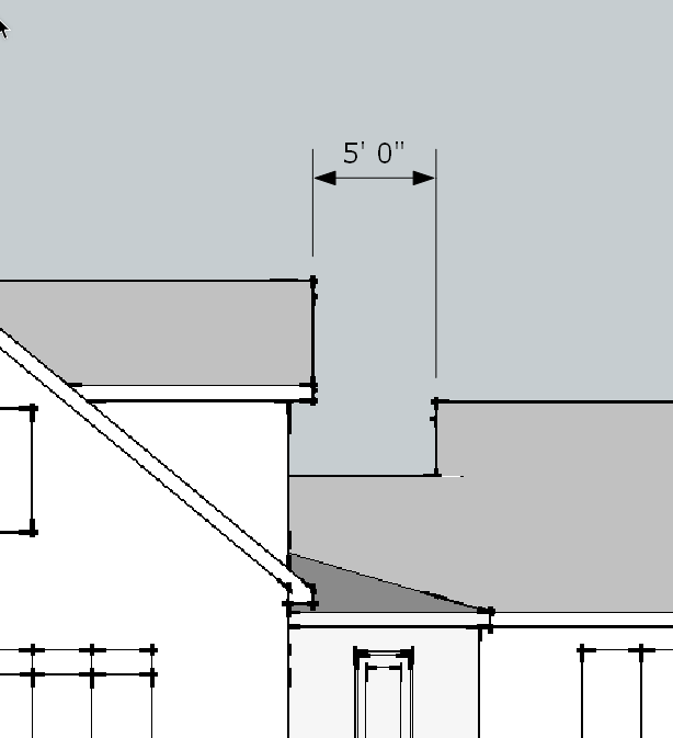
I have been saving the aligned scenes in SU with parallel projection set. It seems that unless I choose one of the standard ortho views in SU, Layout will still interpret the view with 3d information. For simple shapes it is not an issue, but for different geometries Layout picks points in the foreground and background creating unwanted dimensions.
If I am still doing something wrong, someone, please advise.
These files may help clarify my issue
-
Is this what you are trying to get?

PM coming.
-
Yes, YEs and YES
How did you do that?
-
I turned the model to align with the model axes. The Align View thing I mentioned earlier wasn't the right thing in this case although I did sort out a work around with a bit of temporary geometry positioned out from the end of the near gable peak. It's not idea but it works.
-
Though this is an older post and I am wondering if a solution has been found.
This is an issue for me also when creating architectural drawings that are geo-located, and wishing to dimension them in Layout,My current work around is the following workflow
- Geo-Location -> Add Location
- Measure angular offset (A) of a dominant axis of the building floorplan (as seen in the Google Earth Satelite Image) from the Sketchup default Y-Axis
- Make a copy of the Geo-Location Images, and rotate these by the negative angle from previous step (-A). These can now be used for tracing the floorplan etc
- Adjust Solar north by an angle of (-A)
Now I can get orthographic dimensions in layout for the standard views ( but not for any aligned views unfortunately)
Solar North will be correct, as will be Latitude and Longitude.
Drawbacks are the hassle of this workaround and the fact that I am only to get orthographic dimensions from the standard 6 views, whereas elevations offset from these are quite common.See below for a simplified example showing the problem.
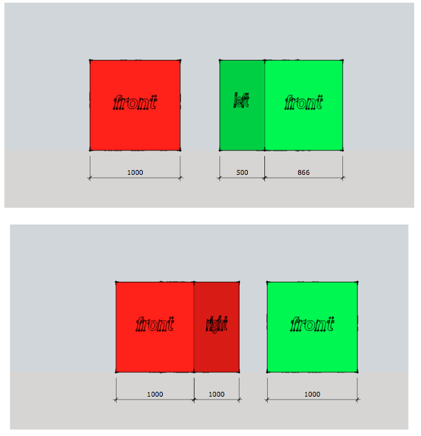
The red box has been drawn with the axis at default orientation, the green box was drawn with axes rotated 30degrees from the standard axis orientation.
The first view is a standard front view using parallel projection, and all orthographic dimensions are correct.
The second view has been aligned to the green front face, and is also a parallel projection. This view also has Ortho activated in the model settings in layout. Note that the red box shows 3d dimensions and not orthographic
Advertisement


