Plugin query - move geometry to layers for export to acad
-
Hi, Is there a plugin to move geometry to layers prior to export so it could be imported into traditional layer-based CAD systems?
I thought I'd seen one here somewhere but can't find it now.
-
What determines which layer the geometry goes on?
-
The plugin I'm thinking of (if it exists) would move the geometry from the objects
(and or Layer 0) that contain it and move it to named layers in the skp file.Currently I manage SU using layers (see attached graphic)
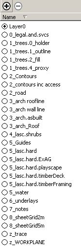
as it's just easier to understand especially
when I move the drawing to Vectorworks or BricsCAD where I (usually) complete my jobs.And currently exporting out as .dwg results in everything exporting on Layer 0, and everything
has to be sent to approprate layers etc, which is a real hassle. So if a better workflow was available
it would be very useful (and worth paying for) -
I don't get that result. If a group is on Layer2 in SU it ends up on Layer2 in my .dwg export--if it is 3d. If I export at 2d dwg. there is no layer information, (no imported layers). Everything is on a new layer "O" (not "0"), go figure.
Also find with 3d export all layers come across with their names except Layer0 which is changed to "0", for whatever reason. It may be a difference in the importing software.
So currently you manage all SU entities with the same layer list you have in CAD, but when you export to CAD you must reassign everything to get it on the right layer?
-
A 2d DWG/DXF is made all on one layer named '0' [NOT 'O' on my setup???]. This is because it's assumed you are making a simple 2d 'graphic', not a CAD file per se...
A 3d DWG/DWF is layered just as the SKP; except for 'Layer0', which becomes '0' - this is because that's the "default layer" name in AutoCAD etc and it's the default name in Sketchup too - ojects inside 'blocks' [components] that are have the default layer behave differently in CAD and in Skethcup.
Note that any 'unused' layers in the SKP are included in the exported DWG/DXF file, but there will be no entities on them, so they'll 'purge' out of the CAD file CAD later if desired.Note that an imported CAD file does the 'default-layer' naming backwards - CAD's layer '0' becomes the SKP's 'Layer0' !
-
Hi and thanks for replies, Well I've just done an export from SU and the result was a .dwg with layers as per the .skp with everything as blocks as per the .skp's solids/components, but all the geometry is still held by the 0 layer. Maybe I'm not holding my mouth right?
So, is there a plugin that will send the geometry from SU's Layer0 back to the layers that hold the objects?
-
In CAD an instance of a block has a layer.
Its definition's contents can be on the default-layer=='0' [when they'll adopt certain aspects of the container] or on any other layers its creator saw fit.In a SKP the equivalent instance of a component can have a layer.
Its definition's contents can be on the default-layer=='Layer0' [when they'll adopt certain aspects of the container] or on any other layers its creator saw fit.
SKP layers don't work like CAD layers so it's advised that 'raw geometry' in kept on the default layer, and other layers are used for the 'containers'.Because component-instances are place-markers for the definition's entities, if you edit the component and change the content's layer to match the layer of the instance then the definition is recast and ALL instances will have their contents on that layer, irrespective of the layer assigned to any particular instance. Hence the advisability of using 'Layer0' for the content's geometry...
It would be possible to write a short script that makes all instances of definitions unique [i.e. only one instance of each one], then give the content's the layer of the container, export the lot and then abort the operation to seamlessly undo the mess-up - the exported file remains as is...
However, even with this I foresee issues... what happens with nested components ? If instance 1 is on layer A and inside it is instance 2 on layer B, when 1's contents are re-layered 2 takes layer 1, then when 2 is re-layered its contents take layer A as well... BUT lets assume 2 is processed before 1... the contents of 2 are re-layered to layer B, then the contents of 1 are re-layered giving 2 layer A but its contents are on layer B ! Confusion reigns.I am still unclear as to why you want to do this... it's not like the CAD version is in anyway unusual - it has the correct layering anyway. You can always edit the block in CAD and re-layer it contents, BUT again if there are instances of the CAD block using different layers then having the contents on anything other than layer '0' will be confusing too


-
The Export to 2D DWG and 3D DWG in SU returns two different results as pbacot said.
- 2D DWG - all elements are moved to AC Layer 0
- 3D DWG - all elements follow SU layering names.
The 2D Export is not creating the desired effect, but it has to be some reason why the 2D DWG Export looks like 2D DXF Export.
Many years ago I used to export 3D DWG files into *.wmf and 'Import' them back through AC's Insert > Windows Metafile... to get 2D representation of roofs, elevations or sections and apply colours or hatch.
Step 1
From SU Export to 3D DWG > and open in AC
Step 2
In AC Export to *.WMF
Step 3
In AC Insert > Windows Metafile... (AC's top menu)Change the view to get plans or elevations.
Use AC command HIDE to hide elements in the background and then export to *.WMFUnearthed, I don't know if the 2D is good enough for you.
One thing's for sure, it keeps the SU layering in the AC 2D drawing

PS. Windows Metafile - was the useful vector based format for Adobe Illustrator, Corel Draw and few other graphical packages, which worked better than the DXF or DWG vectors when imported.
Regards
Hello! It looks like you're interested in this conversation, but you don't have an account yet.
Getting fed up of having to scroll through the same posts each visit? When you register for an account, you'll always come back to exactly where you were before, and choose to be notified of new replies (either via email, or push notification). You'll also be able to save bookmarks and upvote posts to show your appreciation to other community members.
With your input, this post could be even better 💗
Register Login


Advertisement