Sketchup is Inacurrate???
-
This is what I mean...

they come pretty dam close
john -
@gerrit..
fwiw, that thing is nearly impossible to offset manually in sketchup.. good challenge !

-
@driven said:
hey Jeff,
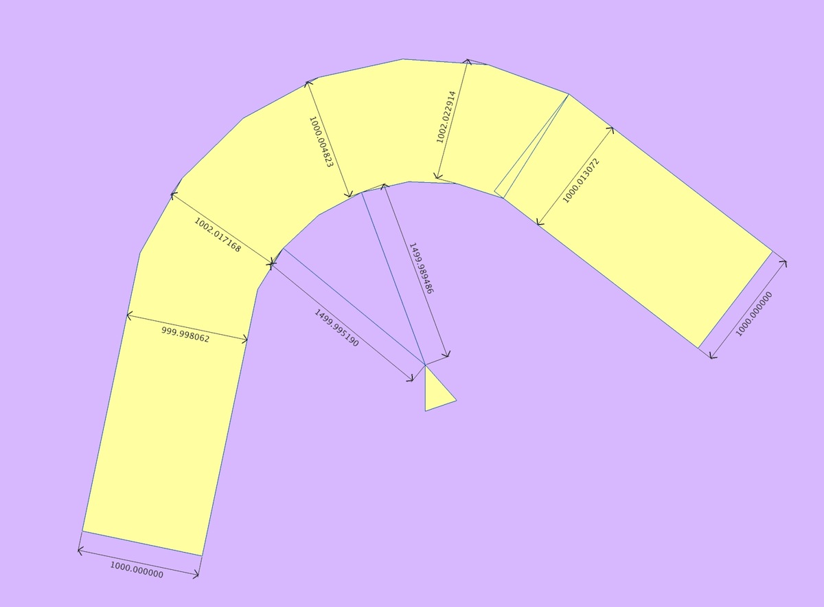
can you see any inaccuracy with my effort, it looks better with more sides, but you can still change those...
johnis this the same one you uploaded a little earlier?
that one has lots of errors in there
all the numbers should be 1.5 or 2.5 for the arc radius (which share the same center point) then 1m for the edge offset..
(your edges aren't parallel either)
-
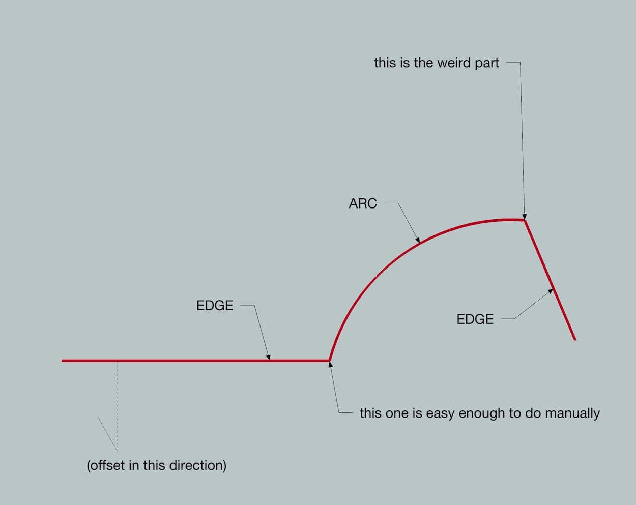
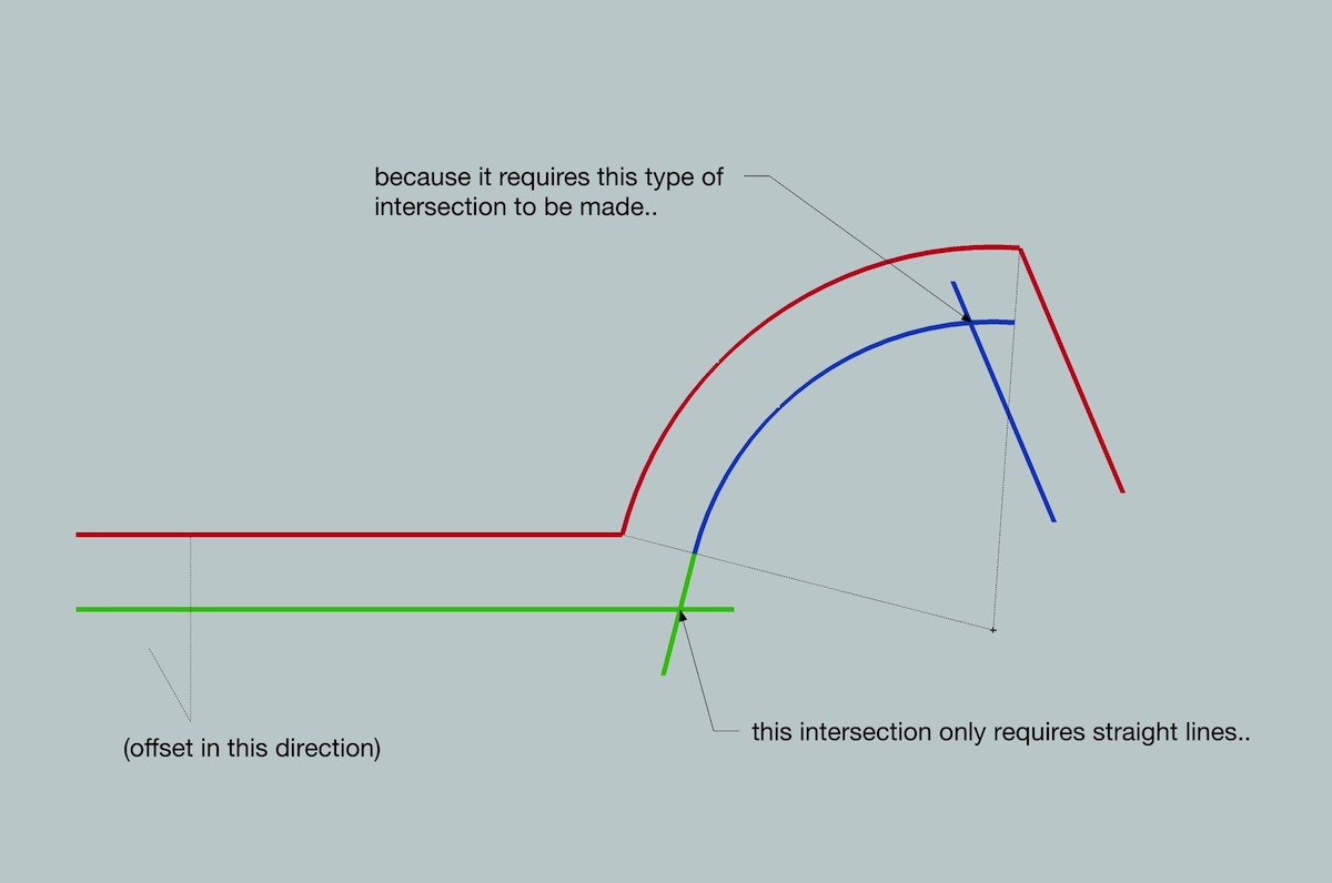
it's not obvious upon opening gerrit's file that it has this weirdness in it.. (ie- took me a while just to figure out why it was acting so weird
 )
)but an exaggerated version looks like this:
-
@unknownuser said:
...
then 1m for the edge offset..
(your edges aren't parallel either)neither of these matter for an accurate drawing, it's the radius and the distance from centre point that all other cad systems care about.
boost the number of sides if you just want it to 'look right', but I thought the point was to be as geometrically accurate as possible with the given tools?
john
-
@driven said:
neither of these matter for an accurate drawing, it's the radius and the distance from centre point that all other cad systems care about.
boost the number of sides if you just want it to 'look right', but I thought the point was to be as geometrically accurate as possible with the given tools?
john
hmm.. i think in this little segment of the thread, gerrit brought up the issue of dealing with offsetting a series of edge-arc-edge when the edges and arc aren't tangent..
but in this situation, the edges are definitely important.. (it's just that they aren't in the discussion that much because sketchup already offsets them correctly..)but making sketchup offset arcs properly then edges improperly.. i think that's probably a worse scenario then what's currently going on

-
@jbacus said:
@gilles said:
and also a circle tool wich works like the rotate tool
I'm not clear what you mean by referencing the Rotate tool. I think you mean you'd like a tool in SketchUp similar to LayOut's Arc tool— with which you set 'center point', 'arc start' then 'arc end'? Is that correct?
john
No, he probably means this: http://sketchucation.com/resources/tutorials/37-beginner/136-aligning-the-rotate-and-protractor-tools#click-drag
I have a feature request filed for this, too.
-
@unknownuser said:
but making sketchup offset arcs properly then edges improperly.. i think that's probably a worse scenario then what's currently going on

@unknownuser said:
If i agreed with you on that. then we'd both be wrong!
Well, this appears to be the conundrum for the all those who oppose changes (i.e. the other side off this argument), and why I say it needs to to a 'new' tool or an 'option' for those who need accuracy, above aesthetics.
I tried to show it can be achieved natively,
however,
as I said earlier, a tool, exposing the centre point and arc end point as rotatable handles with snapping would make this easier.
john -
If you guy's ever bothered looking at my AutoCAD drawing it would strike you what is really going on and what is needed to create an accurate model.
You can clearly see the real arches that are tangentially connected to the two "walls".
The offset red segment is offset perpendicular which is wrong. if it were offset following the radius it would be correct.Because a true arch, being completely round without the facets would have the exact offset value of the 2 units.
Tuning them into facets means you cut off the roundness in each segment, which would make the parallel distance across the facet curves smaller. Still in the vertices the distance stays true to the 2 units. Even if you changed the number of facets the edges follow the true curve, the flat distance in the resulting segments changes with the numbers.Edit: and @ Gerrit, your example is not tangential to both walls. If they were it would be quite clear what is correct. The segmented Arch still needs to act as a real arch not like a polygon. That's why we need a compass tool to display a real circle/ arch then the user can decide what looks better and Sketchup does not need to guess.
-
@desertraven said:
If you guy's ever bothered looking at my AutoCAD drawing it would strike you what is really going on and what is needed to create an accurate model.
Hi, I did look at your autocad image before doing exactly what your talking about in Sketchup, if you overlay it on Gerrit's you'll see it has the same centre point for two true arcs that end cleanly at the fixed wall thickness.
I think there's a actually a rounding of 0.000695mm, so would be interested to know how autocad sees it.
john -
@driven said:
I tried to show it can be achieved natively,
however,
as I said earlier, a tool, exposing the centre point and arc end point as rotatable handles with snapping would make this easier.
johnsee, this could turn into a zillion more pages but it shouldn't.. regardless, the drawing you showed isn't offset properly..
@desertraven said:
If you guy's ever bothered looking at my AutoCAD drawing it would strike you what is really going on and what is needed to create an accurate model.
i tried but i don't understand what you're showing..
@unknownuser said:
You can clearly see the real arches that are tangentially connected to the two "walls".
The offset red segment is offset perpendicular which is wrong. if it were offset following the radius it would be correct.Edit: and @ Gerrit, your example is not tangential to both walls. If they were it would be quite clear what is correct. The segmented Arch still needs to act as a real arch not like a polygon. That's why we need a compass tool to display a real circle/ arch then the user can decide what looks better and Sketchup does not need to guess.
you might of missed the whole point of gerrit's drawing.. it's supposed to be that way.. he's exposing a situation when arc's aren't tangent to the walls.. so if your autocad drawing has both lines tangent to the arc then it's missing the point..
thing is, one offset tool can handle the situation correctly.. it just has to work differently than my other idea of a fix which was to "always move the vertices inward or outward then connect with straight lines"
there's no need for a separate tool because thatwould be goofy.. you should be able to select the perimeter of a house which has straight lines,arcs, curves, non-tangent arcs, all of it.. select the whole perimeter then offset it accurately in one go.. you don't want to go in there and offset each individual portion on it's own.. thats what you have to do now.. so why introduce a new tool which doesn't solve any problems??
especially, when it's possible to fix the current offset tool to where it works right in all situations.. that is possible ..it's not an "either it works right on arcs" or "it works right on edges" type of deal.. it can work right on both..
-
@DesertRaven,
The example was deliberately not meant to be tangent at both sides. (a practical example, not everything is tangent). You wanted code for a solution in all situations (tangent is easy with SU’s native tools). So my question was for you to come up with what a solution should look like. (equal segments, equal nr as parent , practical and nice looking connection on both ends). I certainly don’t know. I do suspect that it’s impossible with a segmented presentation of true arcs.
@jeff,
Your first solution: arc starts at D and ends at K, equal segments, the endpoints in between have nothing to do with the parent arc. Connection at A-side is weird. the other side looks okay at the expence of….. well, measure endpoint to endpoint, something that was so important to you. Not such a good solution.Your second solution chops off the child arc at side B. At best you’ll have a child arc with one less segment, compared to the parent arc. And now its even a curve. Same weird connection on side A.
@driven (John),
It looks like a clean solution, equal segments and equal number of segments for parent and child arc. Even same point at center. But have you measured across, between corresponding arc segement endpoints? And they do not lign up towards the center. Is this acceptable? Jeff brought up examples where vertex to vertex should be equal to the offset. He wanted limited sides and still maintaining fixed offset. Yours is for “nice looking”, not for having accurate predictable measures across, along the segmented arc.It looks like there are more than one versions off a new offset tool for arcs and curves. Some need the vertext to vertex to be equal to the offset. Others don’t mind and just go for same point at center and correct radius.
What I’m saying is you can’’t have both at the same time. So then how could this be coded if we cannot even agree on what IS important in the offset?With multiple arcs (and edges) being connected tangently, this is a whole different matter. You can still offset this “measured vertex to vertex” with SU’s native tools without loosing any information of individual arcs. As long as the offset doesn’t extend any of the radii involved.
This might be a gooud challenge for a plugin. It would speed up offsetting the curve. -
@gilles said:
No what I we want for circle tool is chose center then pick any inference for axis then chose radius
the same way rotate tool and protractor tool work.Sorry, but isn't that exactly the way the Circle tool works today?
edit:
@unknownuser said:No, he probably means this: http://sketchucation.com/resources/tuto ... click-drag
Gotcha- you want to be able to set the working plane without using the inference system.
john
. -
@wo3dan said:
@jeff,
Your first solution: arc starts at D and ends at K, equal segments, the endpoints in between have nothing to do with the parent arc.right, they don't line up.. but, the outer arc is 2.5.. i offset inward a unit of 1.. the new arc is 1.5..
that's the correct solution..i mean, you've exposed a situation which shows that the vertices won't always line up.. the real importance however isn't that.. it's that the offset arc is drawn at it's true radius..
i mean, draw the thing manually.. you'll see how it's supposed to look (or just look at the version i posted
 )
)@unknownuser said:
Connection at A-side is weird.
yeah.. it's weird i think because of how subtle your example is so the solution has just a tiny edge there.. look at the exaggerated images i posted to see what's going on..
@unknownuser said:
the other side looks okay at the expence of….. well, measure endpoint to endpoint, something that was so important to you. Not such a good solution.Your second solution chops off the child arc at side B. At best you’ll have a child arc with one less segment, compared to the parent arc. And now its even a curve. Same weird connection on side A.
again.. the A side connection is right.. i mean, there is a solution to this.. you haven't exposed a scenario which is impossible to offset properly.. and the drawing i posted is actually how it should look..(and more importantly.. the drawing i posted is how it should measure)
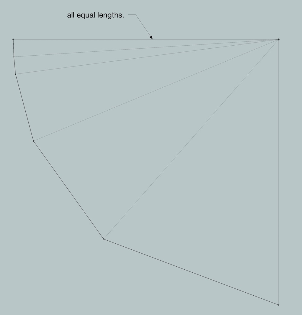
the second solution is just a means of pointing out there are different ways to show it in a polygon modeler.. it's actually the way i'd desire it to look but, that's asking the devs to allow 'arc' entities to have varying segment length as long as all vertices are on radius..
for instance, this is still an arc.. it doesn't matter if the segments are equally spaced.. though allowing this type of arc to be allowed in sketchup would probably confuse more people than it would help..
@unknownuser said:
It looks like there are more than one versions off a new offset tool for arcs and curves. Some need the vertext to vertex to be equal to the offset. Others don’t mind and just go for same point at center and correct radius.
What I’m saying is you can’’t have both at the same time. So then how could this be coded if we cannot even agree on what IS important in the offset?well no.. none of them need to have the vertices equal.. the tool still only has to work one way (mathematically)..
many/most situations, the vertices will line up but it certain situations, such as the one you posted, they wont... but the same exact process applies to both..i mean.. this is not rocket science..
if you offset an arc by 1 unit, the new arc will be 1 unit longer radially..
if you offset an edge by 1 unit, the new edge will be 1 unit away from the first edge..
then intersect/trim as need be..that's all that has to happen
-
@wo3dan said:
Yours is for “nice looking”, not for having accurate predictable measures across, along the segmented arc.
The 'accurate predictable measure' in this example is [r1 to r2] = 1000mm, how more accurate can you get?
It can be measured at the shared central 'cardinal' axis on equally segmented arcs.For an uneven number of segments [r1 - r2] still equals 1000mm.
sorry this is accurate[quote @Jeff (mathematically).. ], any other way is for 'the look'.
john
-
@unknownuser said:
it's not obvious upon opening gerrit's file that it has this weirdness in it.. (ie- took me a while just to figure out why it was acting so weird
 )
)but an exaggerated version looks like this:
[attachment=0:2a9nkqd9]<!-- ia0 -->gc2.jpg<!-- ia0 -->[/attachment:2a9nkqd9]
I don't see that the green section is necessarily supposed to be straight line off the arc. Why? If I were drawing a wall or arched trim. I would extend the arc to an intersection with the line. That's how it would be drawn in a program with real arcs. I can't see a reason to draw it another way, but perhaps you are saying it has some geometric purpose.
-
@pbacot said:
@unknownuser said:
it's not obvious upon opening gerrit's file that it has this weirdness in it.. (ie- took me a while just to figure out why it was acting so weird
 )
)but an exaggerated version looks like this:
[attachment=0:1qiop4ig]<!-- ia0 -->gc2.jpg<!-- ia0 -->[/attachment:1qiop4ig]
I don't see that the green section is necessarily supposed to be straight line off the arc. Why? If I were drawing a wall or arched trim. I would extend the arc to an intersection with the line. That's how it would be drawn in a program with real arcs. I can't see a reason to draw it another way, but perhaps you are saying it has some geometric purpose.
nah. it' would be drawn with straight lines as i've shown..
draw something similar as the red line in cad then offset it and see what happens.. but an offset arc should never get a bigger central angle than the original.. sometimes, you'll have to cut into the offset arc creating a smaller central angle but never larger..
[EDIT] unless you yourself wants to make a design choice to have the inner wall curve all the way to the intersection.. that's fine and probably happens a lot.. but, that's no longer a true offset so you have to go in there and draw it manually per your vision as opposed to using an offset tool
[/edit] -
I am missing the point of Garrits example, why would you solve the corner situation in a none tangential way to start with?
I've designed quite some buildings in my life and facades for wedged buildings too.
Why start out with a not tangential approach in the given situation?
As a designer I would strive to keep the outside wall consistent, and that is what I've been talking about all along, consistency. How ever the miter in the inside results is secondary.But still I would like to be in control of the solution vs letting SU decide.
That is why I'm crying for a compass tool. And so long I'll have to put up with work arounds and plug ins. -
@desertraven said:
I am missing the point of Garrits example, why would you solve the corner situation in a none tangential way to start with?
I've designed quite some buildings in my life and facades for wedged buildings too.
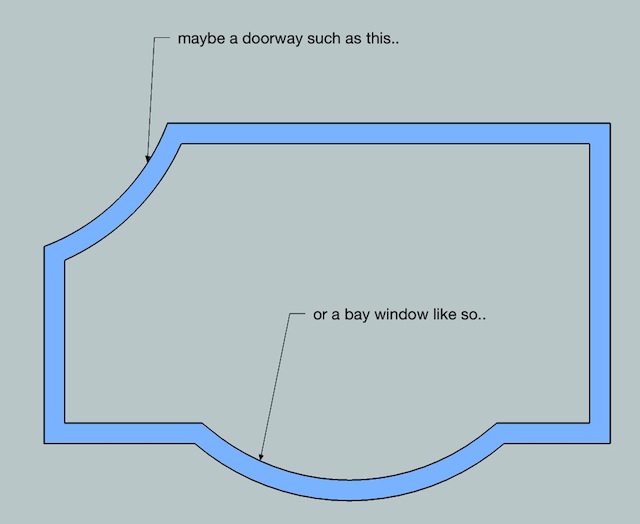
Why start out with a not tangential approach in the given situation?in situations like this maybe?
-
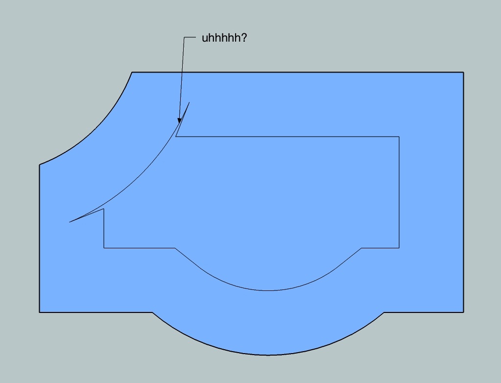
i guess that example leads to this..
if sketchup was offsetting these shapes properly, this kind of weirdness wouldn't be happening with the current offset tool.. and it's not as if they have to deal with the issue separately in order to prevent these spikes (such as what tig's offset tool tries to do..).. if they numbers were right to begin with, these spikes wouldn't happen.. they'd disappear without the devs really needing to do much of anything..
Advertisement


