Sketchup is Inacurrate???
-

Yes / No
-
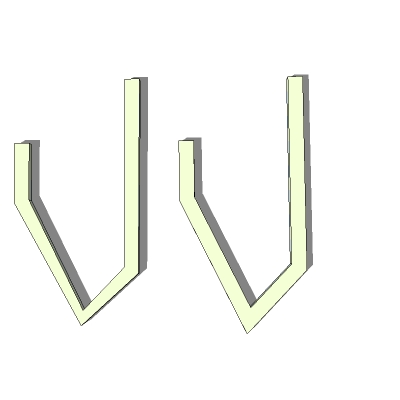
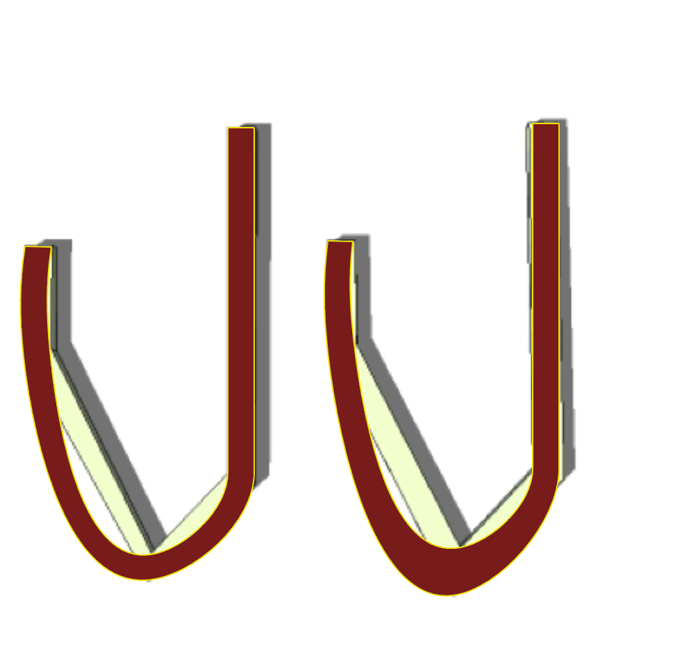
Following that logic. You are saying that the Follow Me version is wrong and the Hammond version is right. Well, how about you apply that to another object that doesn't have regular curves? In this example, the Hammond version is on the left...with a consistent width only at the vertices; and the Follow Me version is on the right...with a consistent width to each side.
Dunno about you, but I know which one I prefer. Yours looks plain ugly.
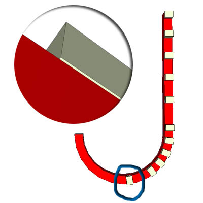
Or putting it another way; here is your J with identical components arranged along its length. Down the stem, they fit perfectly edge to edge...but by the time you get to the bottom of the curve they're hanging over. Isn't that inaccurate too? It doesn't happen with the Follow Me version. You seem to be very partial as to which features you find fault with.
As I said before...both versions are compromises, because of the segmentation of the curve. They are both right and they are both wrong. It depends what your priorites are.
-
@unknownuser said:

Yes / Nono.. it's not a microscopic error in architecture.. say you are designing a circular building.. lets say the building is 80' wall-to-wall (about 24 meters) or about the size of a restaurant..
if you offset 2' in this situation, sketchup is giving an error of almost 1/2" ..the width of your thumb.. (if you offset 100' in this situation, sketchup is giving an error of 20" (about the length of both of your feet.. lined up heel to toe
 )
)it's not an acceptable error.. e_s_p_e_c_i_a_l_l_y for a computer..
[edit- and i should add.. this distance isn't the only error being created.. it's also placing key points (the ends of the arcs) in the wrong place as well..
so you're dealing with both inaccurate offset distances as well as wrongly placed key points.. and those points happen to be the exact points where any subsequent joinery etc for the roof and other key elements will occur..so if i offset the walls (incorrectly using sketchup) which gives me improper joinery.. then say i want to put a domed roof on top whose arcs will be based off the bad points.. then offset those roof arcs.. i'm looking at seriously compounding the errors.. to the point where you could potentially be risking structure collapse..
and this isn't a hypothetical situation.. it's very very real and people NEED accuracy in this situation..
-
You right: Sketching is not Drawing!

-
yet another approach or two attempting to make this clear

in a sneaky way, sketchup itself is telling us that it will not offset arcs for us... (well, the results speak for themselves.. but for those a little hard of hearing, it offers yet another clue)
open your entity info panel and keep it active.. keep the occasional eye on it during this exercise..
draw an arc in sketchup.. entity info names it an arc.. it gives us it's radius.. we can see it's true length
connect the two endpoints then push/pull the surface upwards..
select the curved line of the top surface and look in entity info.. we created a new arc in the drawing
deselect the arc then use the move tool on the middle vertex (cardinal point) to scale the arc..
select the arc then use the move tool + copy modifier to create another new arc to the side..
deselect the arc then use the move to on it's end vertices.. we're now scaling it
or if you'd like, use the scale tool itself to make it bigger or smaller..
rotating arcs works fine too.. you can polar array them if desired creating a bunch of new arcs.
feel free to dimension the arcs at anytime because that tool will also give accurate results like the rest of the above.
now (the punchline if you've been wondering) select the arc and use the offset tool on it..
select the offset and look at entity info ..why is that not an arc?
because it did not offset the arc in the first place.. it (obviously) doesn't know how.. the devs have to tell it how to do it..
@wo3dan said:
For your manually drawn J isn't according to what 'Offset' is about. The meaning of offset in SU (and in other programs that I know)is offsetting edges, not vertices. You offset to the point of where you offset infinitly short edges 0.0000000000000mm and "beyond" (true curves), but always edges. Now you introduce a totally different meaning of the operation, even unknown in other applications, for all I know.
i'm curious to know which other apps act like sketchup in this regard but i don't think it's entirely relevant..
but, in other apps i know which have an offset command, i get the results i'm looking for..
this next example has nothing to do with "oh.. that's a nurbs app.. sketchup isn't" or X-app versus Y-app.. this is only about the geometry and since you guys obviously don't trust me on this, maybe you can trust rhino? i mean, rhino is unarguably one of the most accurate 3D modelers out there and it has a great reputation for it's precision..here is the J in rhino (and in case it's not obvious, i'm using the J because it's a single line and a single arc.. an edge and an arc SHOULD offset differently in sketchup)
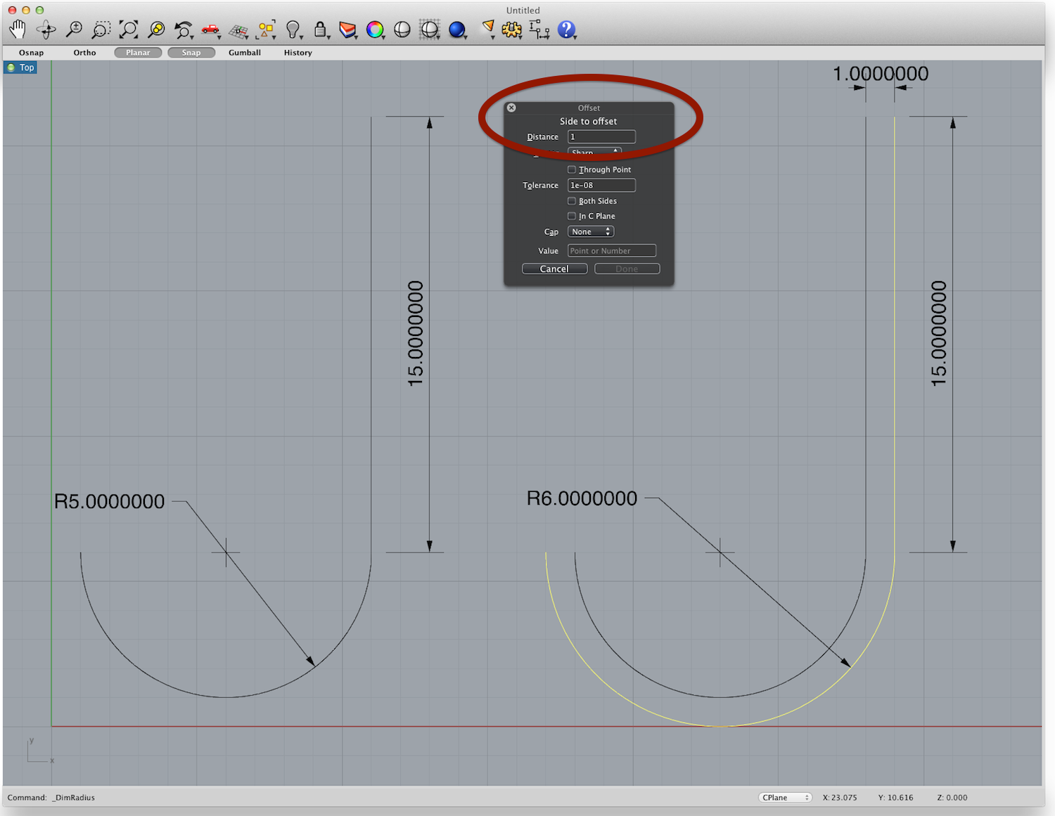
notice the command is called 'Offset' circled in red.. it works more/less like the offset tool in sketchup.. select an edge or series of coplanar edges then choose which side to offset to and enter a distance.. for all i can gather, this is exactly how any type of offsetting should occur in any app of this nature.. (and in my experience, it does.. adobe illustrator is the other one i know that works right.. if i felt it necessary, i bet i could find 100 apps with an offset command that all function the same as rhino's offset)
point is, it's an offset tool in the same exact way sketchup has an offset tool (a broken one).. and it has correctly offset both the straight segment AND the arc.. in one go..
you guys keep alluding to "oh.. this guy hammond is trying to create some unique oddball situation to show some sort of stupid flaw in sketchup"
BUT I'M NOT -- this is super super basic stuff fellas.. i'm sorry.
any time anybody needs to offset an arc, it should be expected to function as shown above..
there are absolutely no excuses as to why sketchup will not draw that J to specs i've outlined in the manually drawn version -or- as proved by rhino (i.e.- my manual version and rhino version are the exact same dimensions)the only thing there is left for you to say that's along the lines of an excuse is "sketchup can not properly offset arcs" (and when you get to that point, you'll also start to realize that follow-me and a host of other tools are also exhibiting this behavior)
-
@unknownuser said:
ok.. about my plain ugly J.. i guess you said that's a J shape being drawn with CURVES other than arcs.. as in, they're not to be constructed using straight boards mitered together.. if that's the situation then truth is, my ugly J is in fact the correct version (well, i didn't see the actual model to measure etc but the method you've outlined is right)... if it's a curved line, even if it's not an arc, then the segments simply don't matter so you'd shouldn't be judging how pretty or not it looks based of the segments.. export those vertex points then break out the french curve and connect the points.. that's the real shape but in sketchup, we can only use the vertices to represent them..
to illustrate the point i was trying to make earlier.. (using rhino to illustrate that point with.. so what..)
if your intention was infact to have your uglyJ comparison representing curves instead of miters (constructed using straight boards mitered together) then i think this will prove that the version you find acceptable is actually the wrong one..
of course, i didn't have a clean 2d output / parallel projection image to work with but i hope this gets the point across.. (and i don't think all you have to do to get the uglyJ version's vertices in sketchup is to bisect the angle then move the vertex on that vector as you would with a segmented arc.. i think you would also have to consider the distance til the next vertex, the one in front and behind, along the curve and have those distances help weigh the position of the offset.. fredo would probably know the right way.. he seems to understand control point manipulation better than anyone else around here..
but even then, i think the above shot does get the point across..
-
Jeff I commend you for the detail. And while I agree with a tolerance of 1/2" in 80 feet is unacceptable on a computer, it is way more than accurate to what is achieved in the field of construction. Industry standards are typically set to 1/8" in 10' for standard tolerance and 1/16" in 10' for precision. This is of course, building construction. Hitting tolerances higher is more suited towards mechanical and industrial design. At that point, a higher level of precision in the software would be required. My guess is that will be achieved shortly.
-
@unknownuser said:
Jeff I commend you for the detail. And while I agree with a tolerance of 1/2" in 80 feet is unacceptable on a computer, it is way more than accurate to what is achieved in the field of construction. Industry standards are typically set to 1/8" in 10' for standard tolerance and 1/16" in 10' for precision. This is of course, building construction.
hey nick,
i've discussed this previously.. (and i don't know if it's in this thread or another.. i bet i've brought these issues up, in some shape or form, hundreds of times in the past 5 years here.)
but, those tolerances need to be set aside for the builders (the guys out there sweating, cussing, drinking beer, etc
 )
)the drawing needs to be accurate though.. because what you're saying is this..
"i'm allowed an error of 1/8" over 10' in my computer... the guys on site are allowed the same"
so, you've just unwittingly doubled the acceptable tolerance.. and that's not acceptable
-
@unknownuser said:
@unknownuser said:
Jeff I commend you for the detail. And while I agree with a tolerance of 1/2" in 80 feet is unacceptable on a computer, it is way more than accurate to what is achieved in the field of construction. Industry standards are typically set to 1/8" in 10' for standard tolerance and 1/16" in 10' for precision. This is of course, building construction.
hey nick,
i've discussed this previously.. (and i don't know if it's in this thread or another.. i bet i've brought these issues up, in some shape or form, hundreds of times in the past 5 years here.)
but, those tolerances need to be set aside for the builders (the guys out there sweating, cussing, drinking beer, etc
 )
)the drawing needs to be accurate though.. because what you're saying is this..
"i'm allowed an error of 1/8" over 10' in my computer... the guys on site are allowed the same"
so, you've just unwittingly doubled the acceptable tolerance.. and that's not acceptable
-
and i'm not sure how much you guys have been paying attention but there is some seriously complex architecture going on out there these days..
and if you put 2 & 2 together, you'll realize that the most important aspect of what makes this possible is the computer.. if we didn't have computers, we wouldn't be able to build this stuff.. period..
it's because computers are so damn accurate and can control and manipulate ginormous amounts of data in a way that's impossible for humans up til now..
so to answer the snide questions that may follow this post, no, i don't expect sketchup to be able to draw these designs..
but-- when people say "oh.. sketchup?!? hahahaha.. that's nothing but a toy and can't be used for any serious work"... well, i'm sorry but they do have a point.. i mean, it cant even do something simple like offset an arc ffs..

-
Since that tolerance is limited to arc off set, that added deviation is even further limited. Even in the most precision construction environments, an 80 foot arc being out 1/4" is much more common than one would imagine.
We all hold to the accuracies of our documents, but the reality to the field more often than not, is " hammer to fit, paint to match".
I'm not knocking the desire for completely accurate drawings. I'm just tempering it with the reality of field construction, where 1/4" deviations are not even considered in overall construction.
-
@unknownuser said:
Since that tolerance is limited to arc off set, that added deviation is even further limited. Even in the most precision construction environments, an 80 foot arc being out 1/4" is much more common than one would imagine.
We all hold to the accuracies of our documents, but the reality to the field more often than not, is " hammer to fit, paint to match".
I'm not knocking the desire for completely accurate drawings. I'm just tempering it with the reality of field construction, where 1/4" deviations are not even considered in overall construction.
justify this all you like.. you're only letting yourself down.. this error is being caused 100% by the way the app is written.. it's not "oh.. well it's natural for us to be seeing these errors.." or "well, that type of stuff is beyond anyone's control" ..this behavior is fully controllable.. fully.
(believe it or not, i am on all of you naysayers side.. the stuff i'm talking about benefits you.. in the context of this internet thread argument thing, it may seem as if it's me VS you (or you or you or you)... but it's not.. it's all of us vs. the developers of the app.. whether you agree with me or not is moot.. and maybe my approach now is to get someone with connections to the suteam (alan winkwink) to disagree with me so much that they'll go to a developer and encourage he/she to come in this thread to shut this lunatic from nyc up
 )
)edit-- hmm.. i may of just wrecked the word moot up there ^.. it sounds right but i don't think i used it properly to say what i wanted.. oh well..
-
@unknownuser said:
I'm just tempering it with the reality of field construction, where 1/4" deviations are not even considered in overall construction.
@nick, fwiw, i don't think it's necessary to describe to me about 'reality of field construction'.. i mean, that's what i do.. i'm a designer/builder..
i do all of the design work then run the show on site.. and i've done so for almost 20 years..
i absolutely know what it's like working on a computer and i know what it's like in the field building those designs...**but since hardly anybody around here seems to believe anything i say, go ahead and pick that statement apart too.. i'm definitely used to it by now...

-
@unknownuser said:
Since that tolerance is limited to arc off set, that added deviation is even further limited. Even in the most precision construction environments, an 80 foot arc being out 1/4" is much more common than one would imagine.
We all hold to the accuracies of our documents, but the reality to the field more often than not, is " hammer to fit, paint to match".
I'm not knocking the desire for completely accurate drawings. I'm just tempering it with the reality of field construction, where 1/4" deviations are not even considered in overall construction.
tolerances aside.. like, lets forget about measurements for this post..
i drew a simple follow me example on pg18 that shows how this behavior kills the ability to draw within the sketchup environment in any meaningful fashion (if you're drawing things other than boxes.. which i happen to do quite frequently)
just considering the inside sections of that follow me result, i should have been left with 8 points for future inferencing etc (2 in each corner)..
instead, since sketchup is broken in this regard, it's left me with 40 points of inference and NONE of them are in the right spot..
and they're all really close together.. who know's what sketchup is trying to lock on to at that point.. of course, i could zoom way in and pick a definite point but like i said, not of them are right anyway so why bother..this point is nothing to do with tolerances or measurements or on site building.. it's about simply trying to draw something simple..
-
Well then Jeff you clearly must see that those tolerances in the field are easily accomplished. If you are working in the field to tolerances higher than those stated, you are alone. I'm not knocking in any way the need for precision, but the reality in the field is quite different from those on our computer screen. To think otherwise in the field of building construction is a mistake. Again, the issue we are discussing is only related to curves, and not octagonal construction, so the implications in real life woul be far less of an issue unless you are Frank Gehry, and then, they are even far less of an issue due to the randomness of the curve in question.
I honestly think, expecting inaccuracies in the field is not letting oneself down, it just prepares you for, and helps you anticipate the uninevitable.
-
@unknownuser said:
Well then Jeff you clearly must see that those tolerances in the field are easily accomplished. If you are working in the field to tolerances higher than those stated, you are alone. I'm not knocking in any way the need for precision, but the reality in the field is quite different from those on our computer screen.
nick man, i'm sorry but you're talking as if you don't really know what the real situation you're trying to describe is..
here's part of something i built last year around this time..
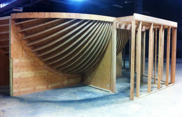
now, when i'm handing out the cutlist to the crew for that, what do really expect me to tell them ??
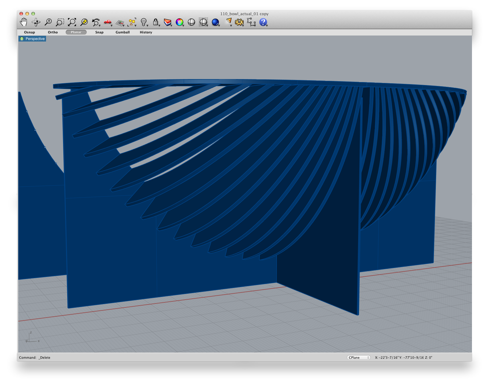
there are 23 different radiuses here and two ellipses.. so, when i'm writing that list, what do you expect me to write?
should i give 7-6 1/4 which is what my computer says.. should i give 7 - 6 as i think it should be.. should i just guess somewhere in between? i mean really, if one of those radii are off a 1/4 when cut, i'll be ok..
but that doesn't have anything to do with me in the situation of giving out the cut lists.. so you're suggesting i should, 25 times in the case of this example, doubt myself about giving out improper numbers here? (and i haven't even got to the part about lengths and angles which also vary from board to board.. this cut list requires over 400 individual dimension.. that's just the curved parts you see in this photo.. on an average job, i would guess i have over 5000 dimensions to transfer from a computer to the job site)
seriously, how should i approach that scenario? do you see how much easier and less stressful the situation would be if i just had the right numbers to begin with?
this is the reality of going from a computer model to an actual construction.. you get the numbers from the computer and you make the list.. that's it.. you don't want to sit around fking with the numbers and second guessing when the computers SHOULD* and CAN* give you EXACTLY* what you need..
does this make any sense? at all?
(fwiw, i did have accurate numbers for building that.. more accurate than humanly possible to make cuts that precise.. and i loved it.. i had zero doubt in the model therefore all energy can be dedicated to building it as correct as possible.. there are many many stresses on a jobsite.. the more you can eliminate, the better the project will be.. computer accuracy is definitely not something that you need to be stressing about on a job site)
*[edit] yes.. i am in fact shouting now...
-
Jeff, there is absolutely no need for the patronising attitude...or the extrapolation to absurdity. You know as well as I do that no architect/designer worth a damn is going to use Follow Me to extrude critical parts of a building around a curve. That tool is quite obviously meant to be used on ducting, railings etc in which the intention is to keep the extruded shape a constant width...something your J example doesn't do...and which your Rhino example (which is supposed to prove God knows what) certainly doesn't do.
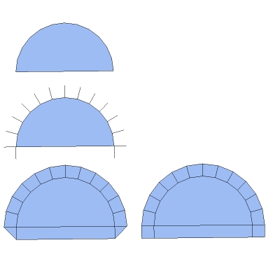
Anyone with any sense at all would lay out a radius-critical construction something like the diagram below before going vertical. This leads to no such contrived broadening at the base. Your solution of the radial splines is fine if your main concern is to maintain such a constraint of distance from centre; but (as my previous example of the arrayed components illustrates) it's not up to spec if your concern is more centred on maintaining a constant profile for the extrusion.
I will repeat it...even if you don't accept it...there are no 100% right and wrong solutions once you abandon true curves for segments.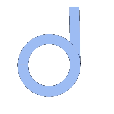
I agree completely with your point about treating curves and straight lines differently; which is why I have been arguing all along for more than a one hit solution for these functions. Offsetting along radial splines along an arc, but a straight linear offset along lines would result in the either of the two versions below. I'm quite certain the non-filetted one would be the most useful and the one that most closely resembles such an offset performed in a bezier environment.
But even here it has to be recognised that this is also a compromise. The offset at the base of that semicircular model is precisely 3"...the offset, similarly edge to edge, along the arc is 1/32" less. True, this will become more accurate if you increase the number of segments in the curve...but by the same token, so does Follow Me. If you increase the number of segments on the base of your J to 36, the discrepancy in the exterior radius shrinks to less than 1/100 mm
-
@alan fraser said:
(which is supposed to prove God knows what)
it proves that when you use an offset tool on an arc in a drawing app that a R5 arc will become an R6 arc upon offsetting it by 1
-
@unknownuser said:
If you are working in the field to tolerances higher than those stated, you are alone.
No, he is not alone.
@ Jeff, do you ever sleep?

-
seriously guys.. i'm done with this thread.. i promise i'm not opening it again..
if a sketchup rep comes in and comments, will somebody do me the favor of notifying me via PM/email..
it's 4am.. i've been arguing about this for 2 or 3 days now.. i know what i know and i know what i need.. if you guys need to view me as "oh.. that dude is off in his own lala land" then that's fine.. (actually, i kinda like sound of that anyway
 )
)good night.. good bye..
Advertisement


