[Plugin] Slicer5
-
@guanjin said:
I use the Slicer5 tool, with the second parameter set; I waited for a long time for the Slices - the reason is the [number of] operations ?
The exported files... Where can I find them?
A form that is that complex with slots etc WILL take a long time to process all of the parts...
It looks like it failed - because there are no proper slots made***.
Is the sliced object very small ?
If you have exported the files initially [OR you do it later] the PNG files are put into their own folder in the same folder as the SKP itself - read the Notes about its naming etc [if you use Pro the DXF files are in another similar folder]. Ensure your SKP's folder has security-rights to be written to by all, so the folder get made.
***Keep the Ruby Console open for any error messages IF it's not working as you expected... -
@tig said:
@guanjin said:
I use the Slicer5 tool, with the second parameter set; I waited for a long time for the Slices - the reason is the [number of] operations ?
The exported files... Where can I find them?
A form that is that complex with slots etc WILL take a long time to process all of the parts...
It looks like it failed - because there are no proper slots made***.Hi TIG
I'm experiencing some problems as well. The slots aren't properly cut, faces are deleted etc. I've attached the file for you to look at.
Cheers,
Joel
-
ivreich
I'll look into your problem SKP.
I suspect it's some issues with 'tolerances' while doing the first slice-set slotting.I'll post a fix asap...

-
I'm Sorry TIG
 I didnt see the XY option. My bad! This is great. Thank you**[b][b]**[/b][/b]
 -
Here's v5.3 http://forums.sketchucation.com/viewtopic.php?p=374969#p374969
A new 'Text-Height' option has been added to the first dialog.
It's been recoded to avoid fails and small 'snags' with complex slotting solutions, that a few of you had reported... -
@tig said:
Here's v5.3 http://forums.sketchucation.com/viewtopic.php?p=374969#p374969
A new 'Text-Height' option has been added to the first dialog.
It's been recoded to avoid fails and small 'snags' with complex slotting solutions, that a few of you had reported...
Slice thickness can not be changed??? -
Sorry guanjin, you [and now I] have spotted a major typo/issue... so an update is in the pipeline...

-
Sorry guys !
Stupid typo in the code means I broke it...
Here's v5.4 http://forums.sketchucation.com/viewtopic.php?p=374969#p374969
-
Thank you TIG!
-
@tig said:
Sorry guys !
Stupid typo in the code means I broke it...
Here's v5.4 http://forums.sketchucation.com/viewtopic.php?p=374969#p374969
Slice thickness and parameter settings are not the same? -
gaunjin
They are quite correct!
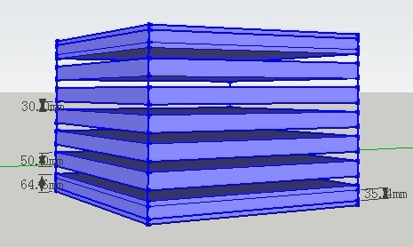
There are 'overlaps' on the slices.You have selected a combination of the sliced-object height [z], slice-spacing and slice-thickness that cause an 'overlap' of slices on the start and last slices.
This is because the slices are always set out from the object's center towards the start/end slices and there will never be a spacing that is more than you have specified.
I assume the spacing is 80mm and the slice is 50mm thick - which gives a 'gap' of 30mm - which you show.
Slices are always placed at the extreme start/end positions, irrespective of the specified spacing.
Because in your combination of dimensions the spacing next to the start/end slice is less than the normal spacing/thickness the adjacent slices are located less than the normal 'maximum' spacing - in your case that actually overlap with the start/end slices. This overlap is ~35mm as your dimension shows - that isn't a slice its two 50mm slices overlapping by ~35mm !
You could delete the start/end slice so that the spacing is consistent for all remaining slices, BUT then the slices won't extend completely from the start to the end of the sliced-object, which results from the specified spacing/thickness not dividing exactly into the object's height !
Alternatively you could remove the overlapping slices near the start/end to have a bigger gap/spacing for the star/end slices.So if you want exact spacing you must make your sliced-object with a dimension that is a multiple of the required spacing, LESS one slice thickness [this because the first last slices are made 'flush' with the sliced-object's extents, NOT centered on them]: so if you want 80mm spacing of 50mm slices in the Z you must ensure that the sliced-object is (N*80mm)+50mm high, where N is the number of slices needed to get near to the required Z-height.
If you have a to-be-sliced-object that must be an exact Z-height, and want the slices to be evenly located using an approximate spacing, then use the new option that was introduced in a recent update.
You simply enter 0 as the spacing, you then get another dialog where you are asked for the number of spaces. The dialog would show something like 'Number of Spaces [Z 800mm]:' - where 800mm is the height of the object, if the spacing needs to be about 80mm and the thickness is 50mm... try 10 number, the spacing will then be (800-50)/10=75mm, or perhaps 9 number for (800-50)/9=83.333mm - you can then choose which spacing suits your needs.As a result of your post I spotted an unconnected glitch when swapping between Space=0 and a dimension - that's fixed and will be posted soon...
-
Here's v5.5 http://forums.sketchucation.com/viewtopic.php?p=374969#p374969
A glitch found when after using Spacing=0, and reverting to Spacing='length', it would stick as an 'integer', not reverting to a decimal 'length' - this is now fixed.
-
A really cool feature would be if you could select a piece of the sliced model and the corresponding flat pattern piece would be (highlighted) selected as well, or vise versa!

-
@xrok1 said:
A really cool feature would be if you could select a piece of the sliced model and the corresponding flat pattern piece would be (highlighted) selected as well, or vise versa!
Unfortunately selecting objects in different contexts is fraught. The two instances are in separate groups for good reasons...
You can, so of do it, if you have your component-edit options set just right when you edit a component instance other instances can appear differently from the rest of the dimmed model; OR you can even have it set so that the rest of the model disappears during the edit, showing only the one being edited and its dimmed sibling in the other context. You can also use the Outliner to select them in turn [the names are the same], and both the SLICE and FLAT groups have the same unique-id code in their name too... -
Here's v5.6 http://forums.sketchucation.com/viewtopic.php?p=374969#p374969
It has two new added Options:
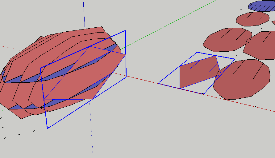
Axis 'A' to make 'Angled' Slices, and Axis 'R' to make 'Radial' Slices - see the detailed Usage Notes...
These tools combined with other sets all saved as Flattened Slices sets, and some simple manual editing of intersecting sets of slices, now lets you have non-orthogonal sets of slices, slotted together... -
Please note that Slicer5 v5.6's new Radial Slice tool is currently limited to work on Sliced Objects placed on the +ve side of the Y axis [Green] - i.e. 'above' the Origin, and which 'straddle' the Y axis [Green].
A more comprehensive version will be available shortly... -
Here's v5.7 http://forums.sketchucation.com/viewtopic.php?p=374969#p374969
The Radial Slices' algorithm is greatly improved, so now there are no limits on where the Sliced Object is placed relative to the Origin [which sets the center of the radial-slicing].
The Angled Slices' +/-ve direction is now corrected, so +ve = ccw and -ve = cw as it should be !
-
Hi TIG!!!
Thank you!!! ... I will try this plugin and see what can I make.
A question: Is there a way to choose a dual axis for radial-slicing [RX/RY/RZ]?Daniel S

-
No, not yet... but you can see the way it's going.

To make slots 'cuttable' and thereafter 'mateable' the axes need to be limited to say 'RZ'... I think.
Even an 'AA' or 'AZ' version would potentially have angled slots or square-cut slots widened to accept the other part...
Thus it gets exponentially more complex at each step...
-
You are right It will be limited to 'RZ'.
I started using and don´t read the instructions... the radially is only from the Origin [0,0,0].
To make this for example I had to rotate the object to get the desired result.Thank you,
Daniel S

Hello! It looks like you're interested in this conversation, but you don't have an account yet.
Getting fed up of having to scroll through the same posts each visit? When you register for an account, you'll always come back to exactly where you were before, and choose to be notified of new replies (either via email, or push notification). You'll also be able to save bookmarks and upvote posts to show your appreciation to other community members.
With your input, this post could be even better 💗
Register Login


Advertisement