Tree surveys and numbering trees
-
Hi, tree surveys are an important part of my work, and in other CADs I've used in the past there's usually been a way of adding a number/label to a tree symbol/block/icon (this is also useful for room, house or any other object numbering).
I've searched high and low and have found nothing like this for skp. I want to use this in sketchup and then send it out with the scenes to LO
 . I include a small part of a typical case - this was only 75 trees but 500 to 1000 or so is not so unusual.
The ideal would be where one can start labelling and have a dialog to input attributes (species, height, health etc) (being able to add to this later would also be very useful). I'm hoping this is possible, and that i can then link it up with Space Design (here's hoping). Is thee a script that does this?
-
Hi Nigel,
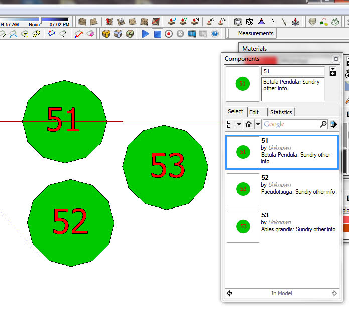
The simplest (but fairly laborious) way that I can think of would be simply to type out all the numbers from 1 to 1000 in 3D text, but with extrusion unchecked. As you do this, a component will be automatically created with the Component definition corresponding to the number you just typed. You could make the text, maybe 10ft/3metres high.You could then open up each component in turn and paste a tree circle into it, underlying the text. All these components will then show up in the component browser and you could save them as a library to be used in different projects. By default, both the definition and description will be the number typed, but it's then a fairly easy (but again laborious) task to to edit the Description field to contain the name of the tree plus any other info required...as in the screen shot below. The attributes of each symbol are then immediately apparent in the browser.
Another method of achieving the same result would be to array 1000 tree circles, then place the sequential numbers on top of each one in turn. You'd then need to select all, explode and purge to get rid of all the existing components. After that, it's a case of just selecting each circle/number in turn and creating a component while manually placing that number as the Definition. You could leave the description field blank until it was needed.
You have to perform the explode/purge bit, because SU won't allow duplicate definition names...you can't have a tree 51 component containing a number 51 component...not unless you actually call it 'Tree 51' instead of just '51'.
-
Thanks Alan
Your last idea is what I might use - very interesting - I could use this with a tablet in the field, - Like you say, tedious setting up, but once you've got the components done it's easy.
I also need a way of entering tree info into components (species, height, trunk thickness, health etc - as individual fields in the component) - does one use dynamic components for this?
There are two main routes that I use for getting tree data into CAD
One - getting a surveyor to record tree position - this results in an Autocad file comprising many blocks (each block representing a tree) and with several attributes attached to each block, e.g. species, x and y position, tree height, tree species, trunk diameter etc (refer to image from autocad (BricsCAD actually))
 The data seems to get lost on its way into Sketchup.
Two - the other route (normally smaller jobs) involves a basic survey (using gridded paper to speed location by eyeball), again I usually collect species, height, girth and plant health, and then CAD it up later. What I'm working towards is avoiding paper, but without buying a robotic thedolite (just seeking a happy medium).
-
Find my ImportDXFtext script.
You need the file as a DXF...
Import the points/geometry normally then the dtext/mtext/attributes etc ?
Keep the CAD origin so the text aligns with the rest... -
I think I would use this approach:
In Top view with no perspective:
Make a circle component (default material)
Make a number with normal text tool (bold 14pt) and group it with the circle comp.
Make an arrowed text and put in on Layer 'Species'
Make another arrowed text and put it on layer 'Info'
Group the circle/number with the texts (one or more texts as needed)
It as also very easy to add more texts if needed, and they can quickly be turned off/on from the Layers panel.
Then I would apply different colors/materials to the groups for different types of trees and/or different states of health.
The advantage here is that the texts will be fully editable, and they will scale so that they will always be readable (although they may appear very cluttered if zoomed out a lot with all texts visible).
I would add texts by copy/paste from a text document with all the numbers, attributes etc.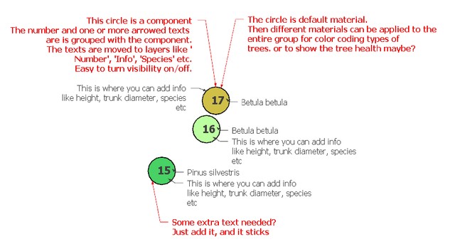
-
Thanks TIG, but that method takes removes the information (the tags) from the dxf - I'm hoping that there's a way to import each block's attribute data into a DCs attributes. Seeing as your script parses the incoming data stream to create the 3D text, would it be possible to create a text block for each icon, from each Autocad Block?
Certainly it does what it says on the tin though, thanks
and yes, you're right it does run for a while -
for my data it was best to do it in batches of 100 icons at a time:

bjornkn, this would work well as a complement to Alan's method above, thanks.
Hello! It looks like you're interested in this conversation, but you don't have an account yet.
Getting fed up of having to scroll through the same posts each visit? When you register for an account, you'll always come back to exactly where you were before, and choose to be notified of new replies (either via email, or push notification). You'll also be able to save bookmarks and upvote posts to show your appreciation to other community members.
With your input, this post could be even better 💗
Register Login


Advertisement