Check out this extremely talented modeler
-
What? The lazy SOB can't model the rest of the car?!
Just kiddin...don't bite my head off.
I thought I was anal retentive when it comes to detailed modeling, and then along comes stuff like this. Impressive. his training is complete. He is now a sketchup-jedi master.
-
@dereei:
I kind of based my comment on noticing the flanges and body of the fuel pump housing had some telltale facets. But the main portion of the work overall is fantastic. -
This is outstanding -- it's so rare to see modeling like this on the warehouse. I couldn't resist doing a clay render with Maxwell.
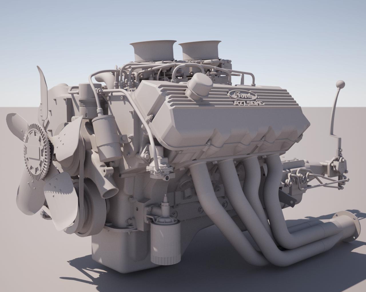
Best,
Jason. -
@jason_maranto said:
I couldn't resist doing a clay render with Maxwell.
Best,
Jason.And I couldn't resist tweaking your excellent clay render

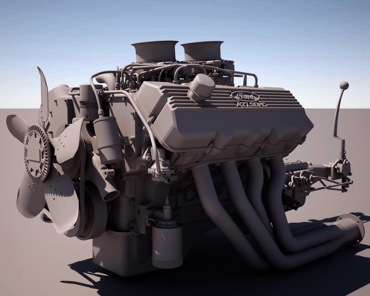
-
Now try applying textures to each part!


-
@tfdesign said:
Now try applying textures to each part!


Textures I can work with -- Rendering is completely beyond me. I hope I didn't offend anybody by playing with Jason's render. You've got to be so careful nowadays

-
When I first saw the Headline of this Thread, I thought for sure it would be featuring ME, but alas. . . twas not to be.


This stuff is just amazing.
I hate him.
JK....


-
No offense taken -- I'm easy

-
Wow, simply incredible. With detail like this there must be one in his garage that needs put back together.

-

-
@turbobrad said:
Wow, simply incredible. With detail like this there must be one in his garage that needs put back together.


(indeed great model)
-
Very nice! with all that knowledge of engine detail you'd think the modeler would know that the 427 is a chev engine though. Ford makes the 429 !?

-
whatever. . .The real question. . .can he come buy and fix my Mazda?

-
@xrok1 said:
Very nice! with all that knowledge of engine detail you'd think the modeler would know that the 427 is a chev engine though. Ford makes the 429 !?

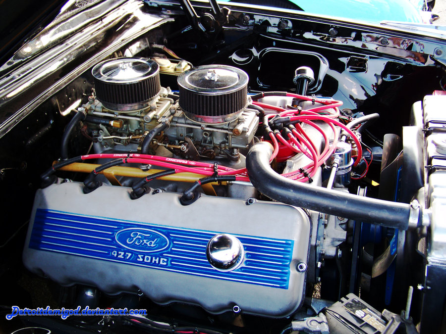
Wiki:
The Ford Single Overhead Cam (SOHC) 427 V8 engine, familiarly known as the "Cammer", was released in 1964 to recapture NASCAR dominance from the Chrysler 426 Hemi engine. The Chrysler 426 used extremely large block casting that dwarfed the earlier 392 Hemi. The Ford 427 block was closer dimensionally to the early Hemis than to the elephantine 426 Hemi: the Ford FE bore spacing was 4.63 in (117.6 mm) compared to the Chrysler 392's bore spacing of 4.5625 in (115.9 mm). The Ford FE's deck height of 10.17 in (258.3 mm) was lower than that of the Chrysler 392 at 10.87 in (276.1 mm). For comparison, the 426 Hemi has a deck height of 10.72 in (272.3 mm) and bore spacing of 4.8 in (121.9 mm); both Chrysler Hemis have decks more than 0.5 in (12.7 mm) taller than the FE.The engine was based on the ultra high performance 427 side-oiler block, providing race-proven durability. The block and associated parts were largely unchanged, the main difference being use of an idler shaft instead of the camshaft in the block, which necessitated plugging the remaining camshaft bearing oiling holes.
-
O-O-O amazing model!

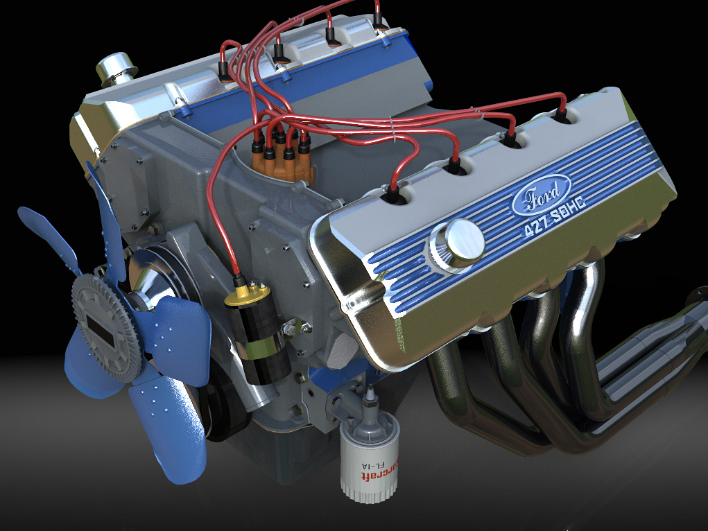
 ... the first very fast test in hypershot
  ...no post prosessing...
-
Wow, very nice! But where are the other two parts of the engine (it's a three-part download)?
-
It's been a long time since I've worked on an engine, and I've never worked on a Cammer, but shouldn't there be bolts here?
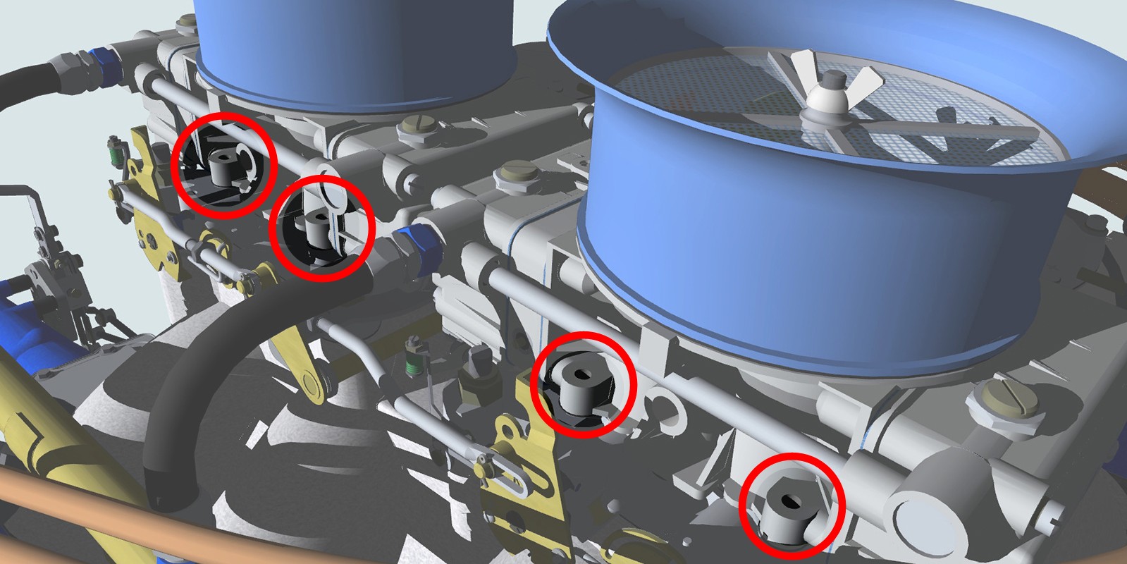
Or is is bolted from below before assembly, and these are just the top of the threaded holes? -
My bad.

Should've know something with that much detail had a real world reference.
-
Hello Everyone...
I'm JMJ-Ohio (Jim Jeffries) and I live in Brookville, Ohio. I want to thank hellnbak for introducing my work to this forum. Did'nt know SketchUcation existed until he contacted me. The "Cammer" was my first real project using SketchUp and I relied more on countless hours at the tube and stubbornness than on talent. The monkey can paint a masterpiece if given enough time and bananas.

I have been involved with machinery and mechanisms for 40+ years, being employed as a mechanical designer and project engineer. I retired 2 years ago, thus allowing me time to catch-up on home projects and play on the computer. But, I rejoined the work force last month so play time will now be very limited.
The Ford 427 SOHC project. No, I didn't have any blueprints or have an engine in my garage. Online research netted numerous technical articles that included critical dimensions and data. I also downloaded and printed hundreds of photos. The combination of known dimensions, proportional measuring of photos and deduced dimensions via detail relationships allowed the picture to come together. A thorough understanding of the function and construction of the subject item is a vital part in allowing the creation of realistic images.
I am pleased with the results of my efforts, but my models are not practical due to their resultant file sizes.
I envy those of you who can create works that please the eye, are portable in size and don't take hundreds of hours to produce. There are many very talented artists and craftsmen out there and when I see their work it encourages me to try harder and learn new ways to do things.Have added a few more screen shots.
p.s. -- no bolts from the top in those carb holes. Your second observation is correct.
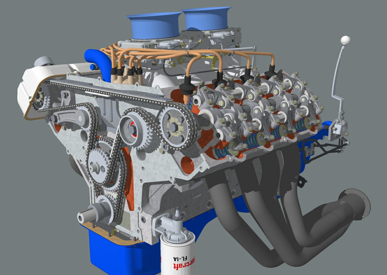
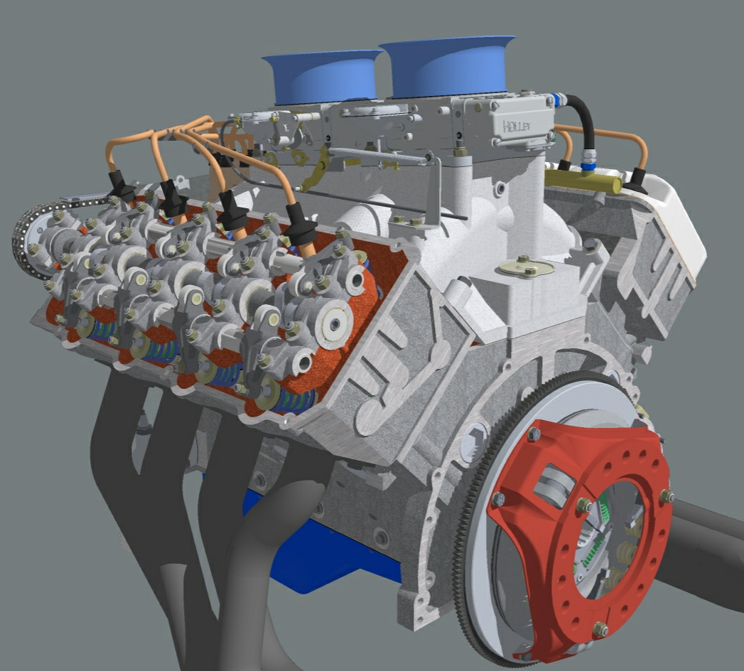
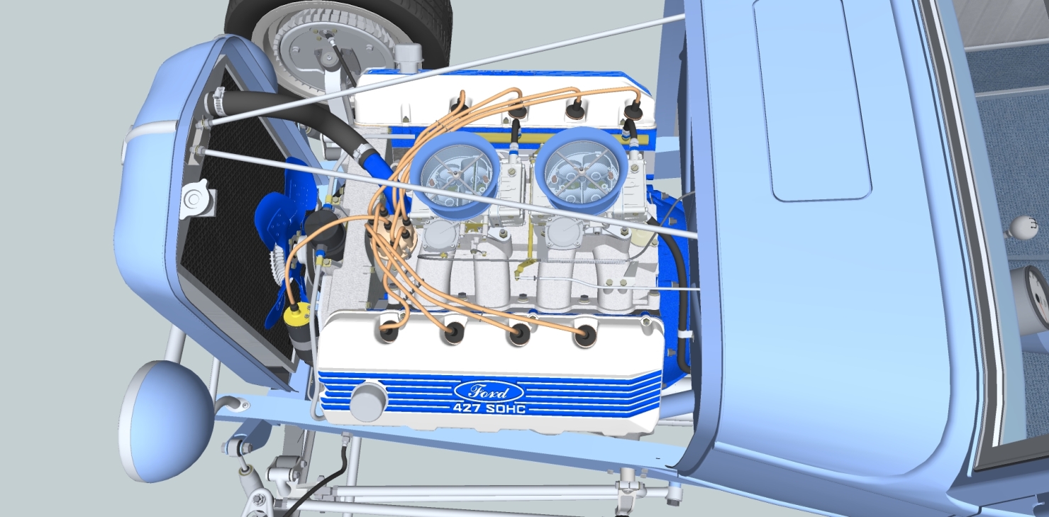
-
Welcome, JMJOhio:
Thanks for responding/ joining. You will find a friendly community here.
Advertisement


