Would you like to sit down? EDITED
-
@jarynzlesa said:
thank you all very much for your consideration
 .
.@unknownuser said:
every single element screwed to footing<<<
actually, every single element will be fixed by bolt and nut with washer. this is not the place of the system where could occur any problem
I'm afraid that's exactly where you will encounter big problems. The problem isn't down/backwards forces, but sideways. With such narrow bands, and no sideways support/bracing of any kind, there will be a lot stress and twisting around those two bolts, and the wood will break very soon. Try with a small cardboard ring and see how very little force it takes to make it fall over sideways when you fix/hold it flat only at the bottom. Making the ribs 25-30cm wide, and fastened with 4 bolts, would help a lot.
Looks nice though -
I have to agree with the others. Very cool design,(very cool) but the lateral forces defeat it. A single connecting cross beam/bar at say, the back curve of the seat bottom, would probably fix that.
-
thank you for consideration.
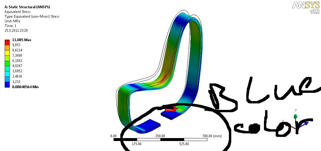
You can see what happen if you laterally load a rib with force 500N on the picture 5 and 6 (Obr_05 and Obr_06).
cheers . -
Intersting concept - your FEA is also interesting but I suspect that you have missed the point of the comments that have been made. I don't think that the strength of the elements themselves is in question. The issue is very definitely with the fixing. Think about how you can use a claw hammer to lever out nails that are otherwise very strong - something similar to that effect could be a problem for your design.
-
I don't know how those stress programs works, but it looks like everybody else here thinks that the construction will not work very well without any lateral/sideways support.
Like on this little image.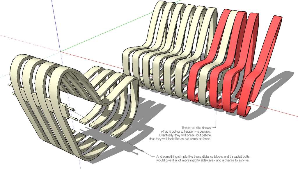
-
Here's an example of a similar concept, the Scandia chair.
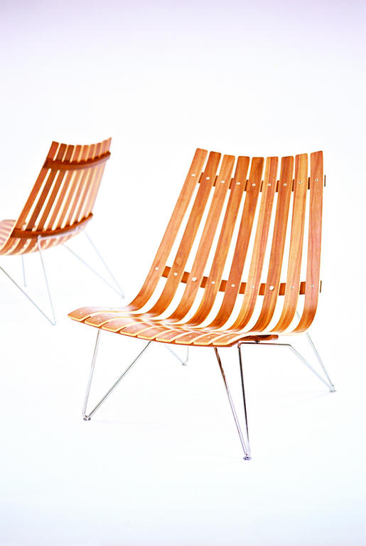
As you can see - lots of lateral support.
-
thank you for comments.
@john.warburton said:
I don't think that the strength of the elements themselves is in question.
it was a question. solved.
@john.warburton said:
The issue is very definitely with the fixing. Think about how you can use a claw hammer to lever out nails that are otherwise very strong - something similar to that effect could be a problem for your design.
this is why i made FEA.
@bjornkn said:
it looks like everybody else here thinks that the construction will not work very well without any lateral/sideways support.
Like on this little image.[attachment=1:2bvrvpb6]<!-- ia1 -->bench.jpg<!-- ia1 -->[/attachment:2bvrvpb6]please, look a little bit closer to ansys outputs and you find out that the situation, you draw with red color, could not happen.
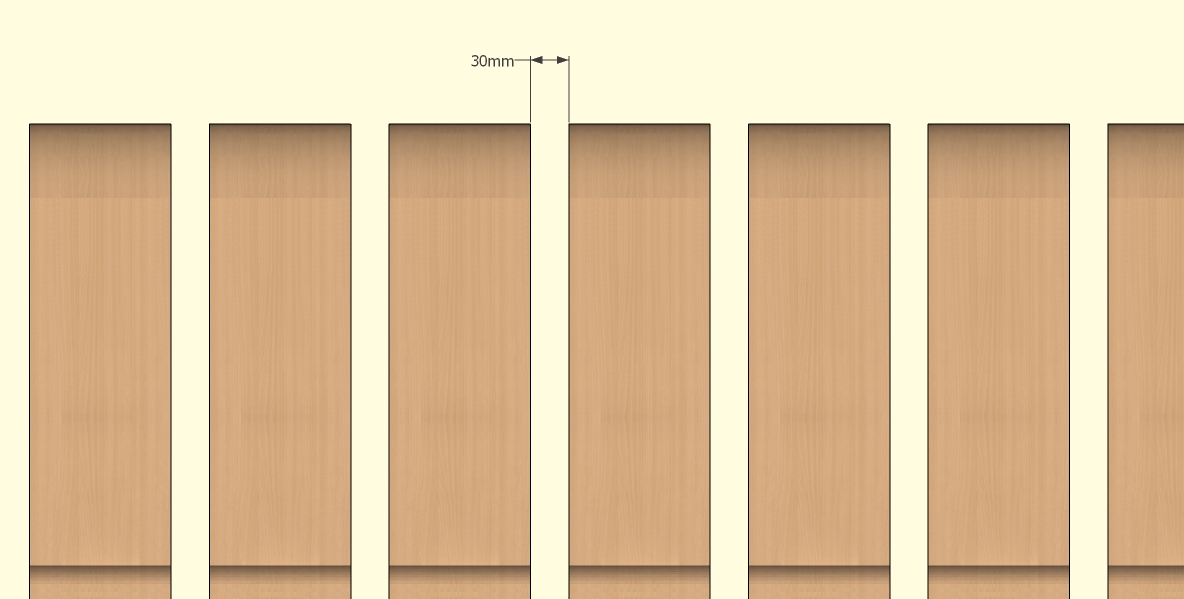
variant with distance block, you draw, would made structure more rigid. but the ribs are supposed to be flexible. distance between ribs is 30mm.@bjornkn said:
Here's an example of a similar concept, the Scandia chair. [img]scandia_lounge_2.jpg[/img]
As you can see - lots of lateral support.scandinavian furniture's design is always inspiring, e.g. peter opsvik's work.
-
@jarynzlesa said:
please, look a little bit closer to ansys outputs and you find out that the situation, you draw with red color, could not happen.
Well, all commments here disagree with Ansys.
Did you tell Ansys that these ribs are fixed with 2 small points/bolts at the ends of the rib, made of laminated wood with fibers mostly following the curve, and that constant flexing/twisting may also eventually lead to water penetrating into the wood around the bolt holes and maybe cause rot?
There are no indicators on the Ansys charts to show where the fixed points are located?
Have you had an engineer or carpenter look at the design? -
here's a little project for you:
- go drill 30 3/4" holes in concrete
- report back with redesign
-
hi,
I do like the design...
having consulted on a number of 'street furniture' contests I'd like to suggest you consider 2 fairly common requirements.
installation time- simply how long will it take to erect on site [minimum being best]
cleaning and maintenance around the 'object' [hosing, sweeping, mowing, etc.]
with these in mind,
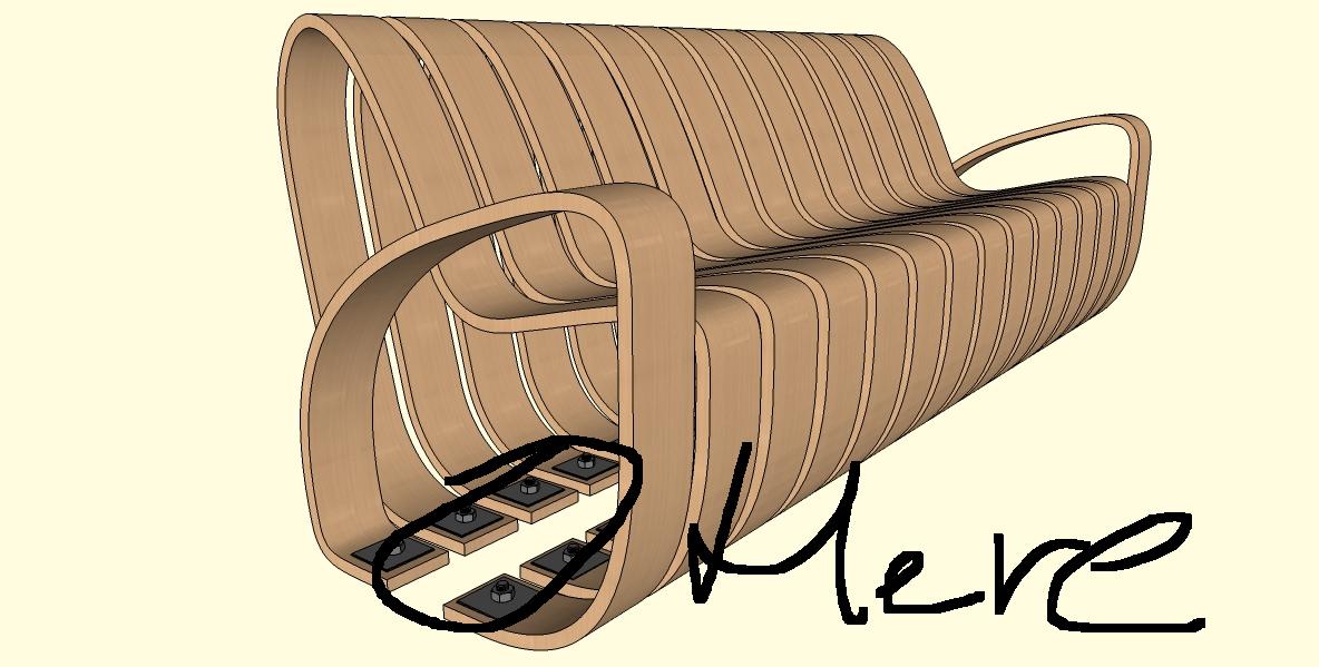
I think you could incorporate a footplate extrusion which allows for pre-construction, rising off the actual substrate and include spacers to alleviate some of the stability concerns raised in this post. The attached image is simply to explain what I mean, not an attempt to hijack your design.
john

-
@bjornkn said:
Did you tell Ansys that these ribs are fixed with 2 small points/bolts at the ends of the rib, made of laminated wood with fibers mostly following the curve
yes of course. without that, the calculation would be completely useless.
@bjornkn said:
and that constant flexing/twisting may also eventually lead to water penetrating into the wood around the bolt holes and maybe cause rot
there is no way how to take into consideration these factors. maybe use some coefficients. calculation is made with perfect material (just like you describe before).
@bjornkn said:
There are no indicators on the Ansys charts to show where the fixed points are located?
@bjornkn said:
Have you had an engineer or carpenter look at the design?
one mechanical engineer and one woodworking engineer.
@driven said:
hi,
I do like the design...
having consulted on a number of 'street furniture' contests I'd like to suggest you consider 2 fairly common requirements.
installation time- simply how long will it take to erect on site [minimum being best]
cleaning and maintenance around the 'object' [hosing, sweeping, mowing, etc.]
with these in mind,
I think you could incorporate a footplate extrusion which allows for pre-construction, rising off the actual substrate and include spacers to alleviate some of the stability concerns raised in this post. The attached image is simply to explain what I mean, not an attempt to hijack your design.
john
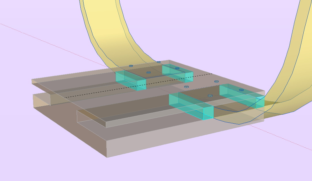
brilliant idea and you are right (installation time, maintenance, lifetime, etc.). thx for pic - one picture say more than a hundred words
. -
@bjornkn said:
I don't know how those stress programs works, but it looks like everybody else here thinks that the construction will not work very well without any lateral/sideways support.
Like on this little image.[attachment=0:gl9mkt48]<!-- ia0 -->bench.jpg<!-- ia0 -->[/attachment:gl9mkt48]Exactly. And by hiding the cross brace, you still maintain the openness that makes it so cool.
Any lateral movement of this design is dangerous to the user. Limbs/extremities can and will get caught between the expanded gaps that will be created by lateral forces.
-
Very nice looking concept. I do have some questions for you. I don't expect answers but just for your consideration;
- What is the rational for the allowables. It would seem to me bending wood will have a considerable variations. Wood is some what like a composite so are there any requirements on moisture content control in the process of allowable establishment ;
- What knock down factors are used for the bolt holes;
- What muff factors are you required to use as you go form preliminary design to final drawing release. You should probably have say about 1.3 at start and 1.1 at end;
- Are any proof load test planned as part of build.
- What is the rational for the design loads. It seems to me the 180 lb force ( 800 nwt may not be adequate given the multiple seating). That is the reason for the muffs. Once you have all the allowables established then a total FEM with multiple loads will result in some elemnets loaded more that others ? You will assume differnt modulus and allowables etc for the elements?
- What is the rational for one load at a time vs x,y,z ( children playing adults seated and leaning etc. ?)
-
1)12,9MPa – compressive strength (radial); 55,5MPa – compressive strength (longitudinal); 109MPa – bending strength; 11,6MPa – shearing strength;
w = 12% ; for beech – composite will have better properties.
2)Sorry, I don’t understand at all. Knock down factor – what does it mean?
3)Sorry, I don’t understand at all. Muff factor – what does it mean? Don’t know what muff is.
4)It is a standard.
5)800N (180 lb) on one lamella. Maybe, it’s too much.
6)X = 500N, Y = 800N, Z = 800N

-
@jarynzlesa said:
1)12,9MPa – compressive strength (radial); 55,5MPa – compressive strength (longitudinal); 109MPa – bending strength; 11,6MPa – shearing strength;
w = 12% ; for beech – composite will have better properties.
Sorry did not mean for discussion.
FYI: The question is you have allowables ,but where did they come from and how good are they. Composites are not by definition " better". They are very process sensitive and not like metals and you can not depend totally on text book values. You have to look for bonding voids, moisture control etc. We would run ultra sound and proof test etc on each item we build. Of course we were building for some rigorous application. Ask the aircraft engineers what they do for composites on planes they build.
2)Sorry, I don’t understand at all. Knock down factor – what does it mean?
When you have bolt holes etc. one gets a reduction in strength ,so knock down factors are applied to account for such things. For example in your case the bolt holes cause a material reduction so do you use the same strength there?
3)Sorry, I don’t understand at all. Muff factor – what does it mean? Don’t know what muff is.
When one normally starts a design there are some unknowns. For example the material properties, loading etc. There is typical a 'muff'( sorry for the slang) aka safety factor will be applied at the start and then that is reduced as one goes through the design process. So say at the very start you may have a 1.3 and then when the drawings get final approval it may be reduced to 1.1. The values we used were established either by the customer or the chief engineer.
4)It is a standard.
5)800N (180 lb) on one lamella. Maybe, it’s too much.
6)X = 500N, Y = 800N, Z = 800N -
@mac1 said:
There is typical a 'muff'( sorry for the slang) aka safety factor
hmm.. where i come from, muff means something totally different and in the case of this particular bench design, i'd be more concerned with the ball factor as opposed to the muff factor.
-
John's illustration illustrates exactly what I suggested in my original crit...a steel spine running along the base with all the members slotted into it, so that it would require much fewer fastenings into the concrete. But your response was:
@unknownuser said:
It will definitely stay how it s designed.
???

-
@mac1 said:
FYI: The question is you have allowables ,but where did they come from and how good are they.
http://wood.mendelu.cz/cz/sections/Props/?q=node/56 good source
@mac1 said:
Composites are not by definition " better". They are very process sensitive and not like metals and you can not depend totally on text book values.
they have better properties than just a wood, that's why they are made e.g. glulam, paralam etc.
@mac1 said:
You have to look for bonding voids, moisture control etc. We would run ultra sound and proof test etc on each item we build. Of course we were building for some rigorous application. Ask the aircraft engineers what they do for composites on planes they build.
it's about ensuring quality in technology process, I don't want to build a plane - it is just a bench.
@mac1 said:
We would run ultra sound and proof test etc on each item we build.
it's a little bit expensive, isn't it
?@mac1 said:
When you have bolt holes etc. one gets a reduction in strength ,so knock down factors are applied to account for such things. For example in your case the bolt holes cause a material reduction so do you use the same strength there?
it is not the spot where the lamella could crack first.
@mac1 said:
When one normally starts a design there are some unknowns. For example the material properties, loading etc. There is typical a 'muff'( sorry for the slang) aka safety factor will be applied at the start and then that is reduced as one goes through the design process. So say at the very start you may have a 1.3 and then when the drawings get final approval it may be reduced to 1.1. The values we used were established either by the customer or the chief engineer.
you meant safety coefficient, I suppose. in this case the muff factor is 4,2 than.
@unknownuser said:
hmm.. where i come from, muff means something totally different and in the case of this particular bench design, i'd be more concerned with the ball factor as opposed to the muff factor.
maybe in another dimension.
@alan fraser said:
John's illustration illustrates exactly what I suggested in my original crit...a steel spine running along the base with all the members slotted into it, so that it would require much fewer fastenings into the concrete. But your response was:
@unknownuser said:
It will definitely stay how it s designed.
???
not any more please
 .
. -
Like I have said more than once I was not looking for any answers, was trying to give you some items to think about and gee I did not know you were not building an aircraft. I also specifically stated my experience base came from more rigorous applications. You are the final designer and will have to take full responsibility for the design. You need to under stand (if nothing else) composite designs can be very good but they are only as good as the process controls in the build. It is NOT like buying some metal part. You must consider the effect the attachment methods have on you design.
-
thank you all for your consideration and comments.
Hello! It looks like you're interested in this conversation, but you don't have an account yet.
Getting fed up of having to scroll through the same posts each visit? When you register for an account, you'll always come back to exactly where you were before, and choose to be notified of new replies (either via email, or push notification). You'll also be able to save bookmarks and upvote posts to show your appreciation to other community members.
With your input, this post could be even better 💗
Register Login


Advertisement