Help for Stair
-
Dear forum members,
I would like to construct a wooden staircase but I'm having trouble with the steps in the corners. I don't know right how to design these transitional stages. Any help would be appreciated.
Charly
-
You haven't quite approached it as a stair designer would

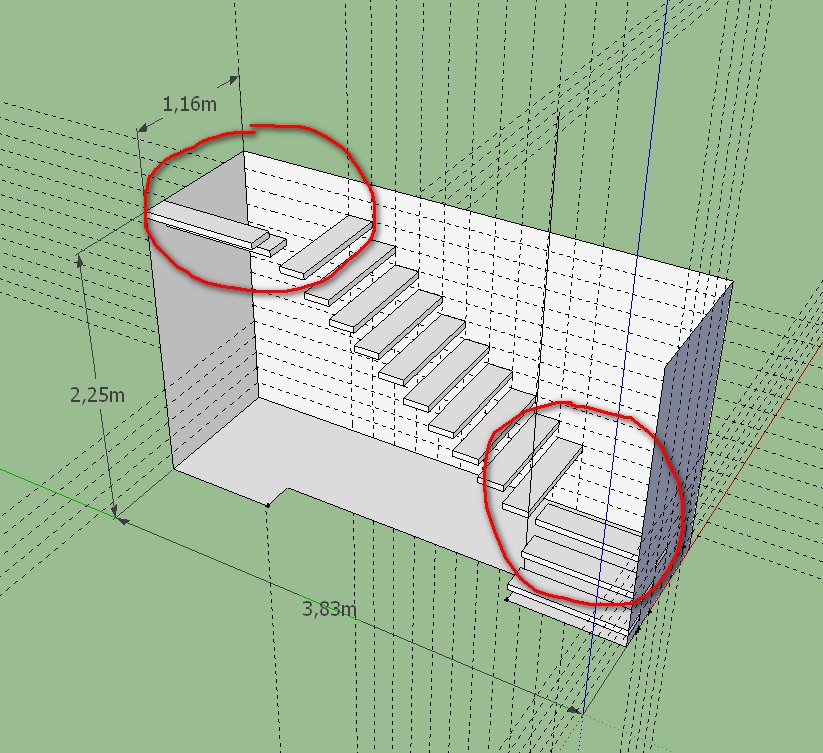
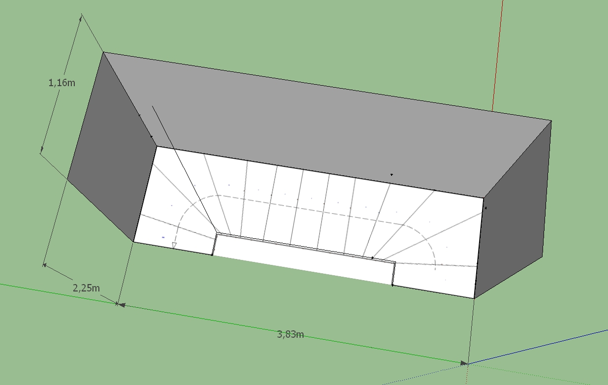
You know the number of 'risers' in the height [18].
You know the 'going'.
You know the fact that the two ends start in opposite directions and that most of the stairs is at 90 degrees to those.
Now what you have made so far shows that you will need to have 'tapering-treads' to sweep the flight around the two corners.
[Had you given a little more space to the stairs you might have avoided tapered-treads by having landings near the top and bottom with 2 steps up each and the rest in the main flight].
Depending on the type of staircase, width etc there are Regulations about how tapered treads work.
I'll discuss typical UK domestic stairs here, but I'm sure the rules are similar in most places...
The tapered tread can't be less than 50mm at it's thin end.
Let's say the normal straight-tread is ~0.9m wide then measuring from the narrow end ~0.450m the tapered-tread's going must be the same as the going of the other straight-treads' - this dictates the angle in plan for each tapered-tread.
Please note these concerns too...
Your going is 200mm which is too little - 230-250+ would be more common
Your rise is 150mm which is unusually small - 180-190mm max for domestic is common and 170mm max for semi-ambulant disabled access...
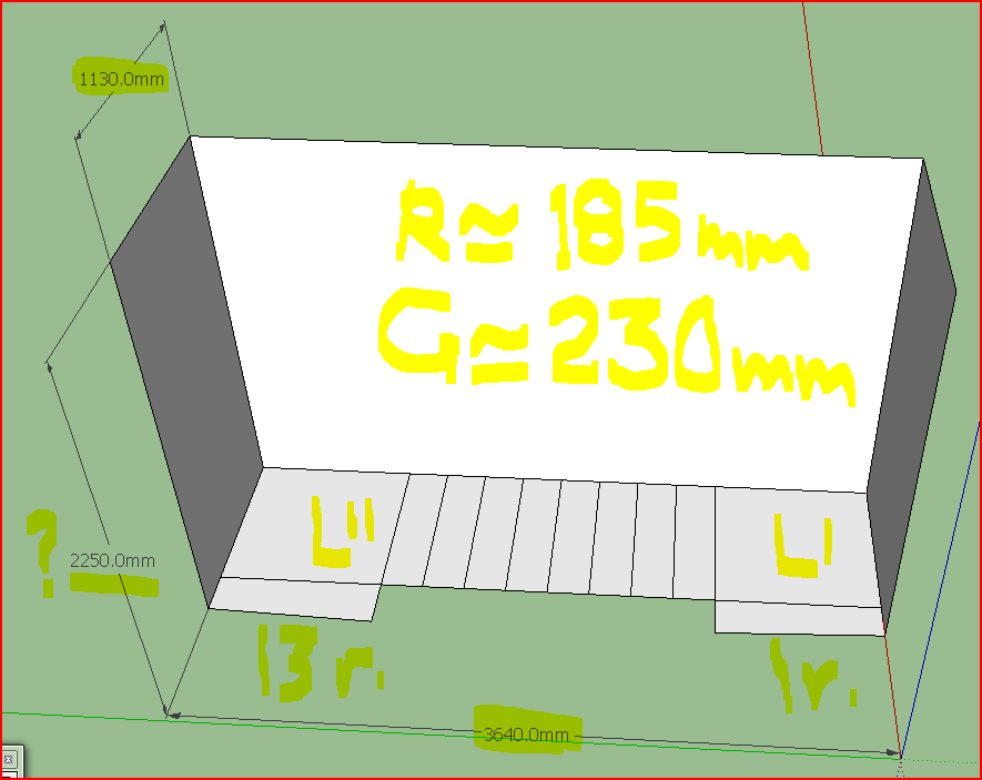
Your floor-to-floor height shown at 2.250m is very small - a domestic ceiling height of 2.3m is minimal and 2.4m more common, with a fl-fl of ~2.6/2.7m. At 2.6m gives 14 risers at ~185mm each... [you showed 18?]. At 2.25/2.3m you'd only need 12/13 risers ??
There is also a rule for the pitch [slope] of the stairs 2R+G>=550mm<=700mm - this ensures that the pitch of a flight is neither too steep or too shallow: so with a ~185mm rise the going needs to be 185+185+230=600 >550 <700...
I also note than you haven't overlapped the treads - this is typically 20mm - so the 'tread' size is 20mm bigger than the 'going' size when viewed in plan.
You need to draw the stairs 'flat' in plan to work out how the tapered-treads work.
Then make the 3d form from that.
-
Hi TIG
Thank you for your detailed instructions. Maybe I expressed myself wrong. I was looking for a technology to produce this corner treads.
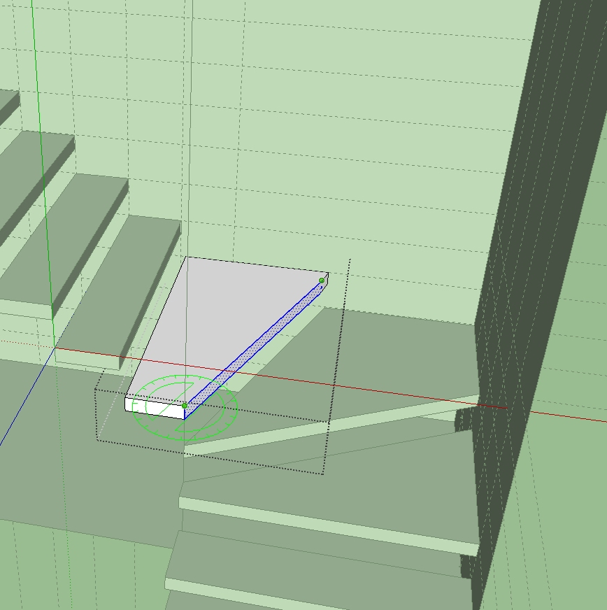
I tried it with rotate face, Maybe there are better solutions.Charly
-
@charly2008 said:
Thank you for your detailed instructions. Maybe I expressed myself wrong. I was looking for a technology to produce this corner treads.
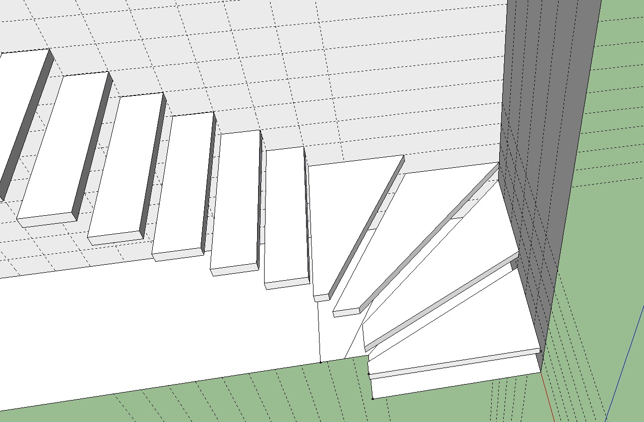
I tried it withrotate face, Maybe there are better solutions.Don't understand. Typically there is a square landing when the steps change direction (by 90 degrees). But when you suggest
rotate face, I visualized the following: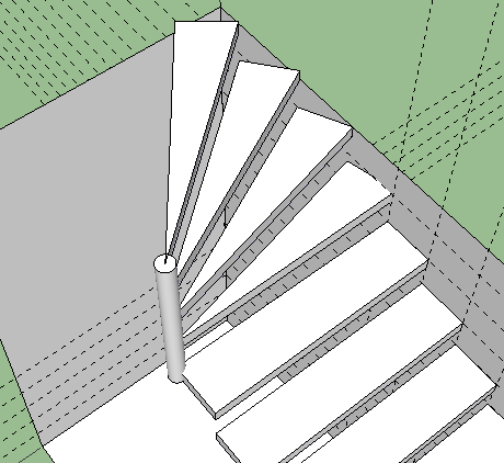 This arrangement is dangerous because the "go" of the thread closes to the outside edge is almost zero. In my part of the world, this is not allowed.
 -
Opps, you posted while I was drawing. The problem remains in your step. It is easy to slip and fall if you place your foot on the "go" that is zero.
-
CharlyWhat you illustrate is the correct way to form those 'corner-treads'.***
What I was trying to show you was that you didn't need them with the constraints you showed - a square landing would work...
But IF you corrected the fl-fl to something more likely AND you constructed the stairs according to accepted norms then you'd need to make 'tapered-treads' in the corners.
There are general rules for calculating these.
You haven't followed them.
***Your illustration does show the correct way to model this type of treads... BUT what you'll get won't pass the likely regulations - or if there are no regs then they will just be awkward/dangerous to walk up/down...
So I suggest you take some early decisions about making a compliant set of stairs... and then model them in 4d from a simple 2d interpretation... Otherwise you'll end up with an almost convincing set of stairs that would never get built in reality.......EDIT: Honoluludesk's version doesn't work as the tapered-treads are to small at the thin end [you could fall an kill yourself! - hence the UK min. 50mm rule]. Also the tread dimension at its center should be equal to the tread size on the rest of the 'straight' flight... Again making it anything else might cause a stumble - especially if it's less......
-
I thank you for the efforts that you have made. The staircase is only for a wooden house model. I have looked at the plan again and I think so it fits.
-
It is 'made' correctly in the SKP... BUT the going measured on the center of the tapered tread isn't the same as the going on a straight tread... so it isn't 'safe' !
There are rule a bout making a staircase safe to use - yours isn't right.
-
Charley
Save yourself some grief and just download the all the stair scripts from the following:
http://rhin.crai.archi.fr/rld/plugins_list_az.php
Good place to start and you can just do the "winders"
in place of the landing on the "U" type stair.
Also look up stair layout on the web for some stair basics.
(Uniform Building Code a start)
http://www.blocklayer.com/stairs/stairseng.aspx
http://www.stairplan.com/winderplan.htm
Hope this helps a bit.
dtr
-
It looks like you are doing log construction. Why don't you do the steps out of logs split down the center? Winders are a finished carpentry that may not match the overall design.
-
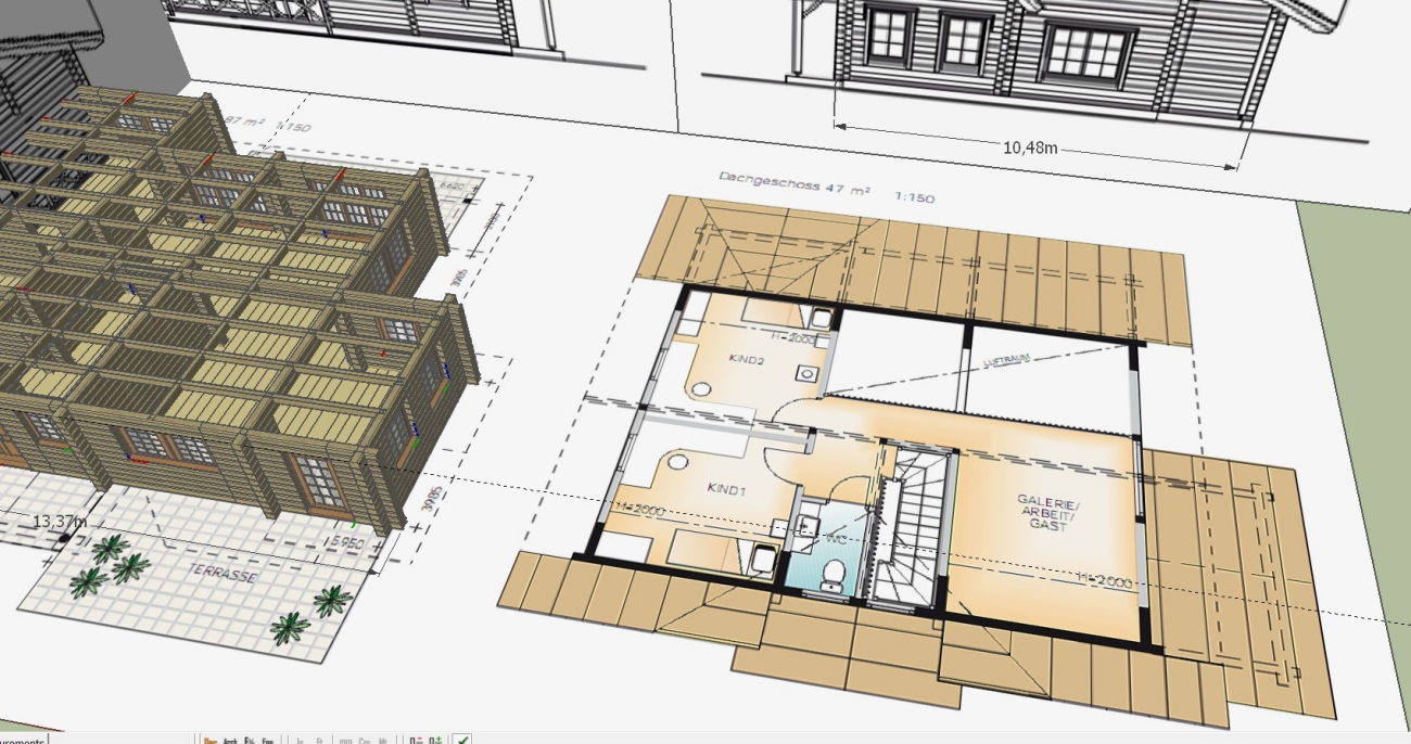
Hi,
thanks again for your help.
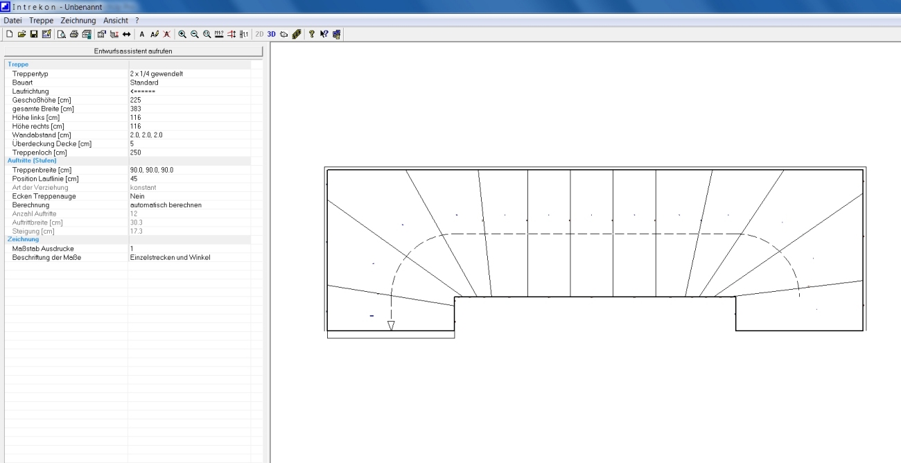
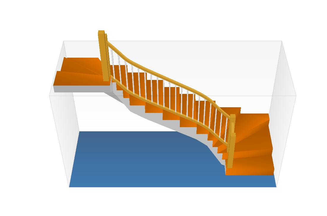
One thing I've learned by now that the stairs calculation is very complex. Especially when one has to learn all the technical terms. I have now found a demo program for the calculation of stairs. Unfortunately you can not export the models in the demo version. Therefore, I imported a snapshot of the plan into Sketchup.
Charly
-
Great!
As you can see from the resultant images making a compliant staircase with tapered treads etc is far from easy...
As you say, you can now take the plan image, import it as an Image and Scale it [TapeMeasure tool] to the correct size; then use it as a basis for making the stairs...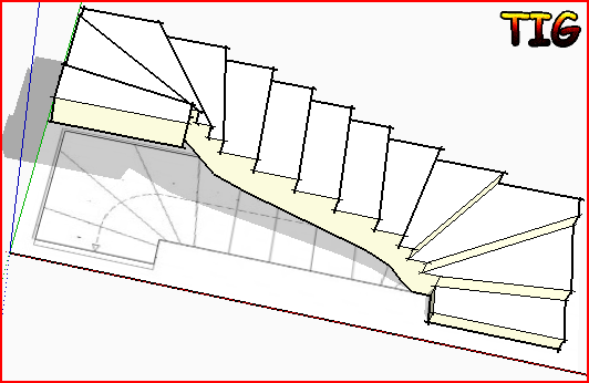
Hello! It looks like you're interested in this conversation, but you don't have an account yet.
Getting fed up of having to scroll through the same posts each visit? When you register for an account, you'll always come back to exactly where you were before, and choose to be notified of new replies (either via email, or push notification). You'll also be able to save bookmarks and upvote posts to show your appreciation to other community members.
With your input, this post could be even better 💗
Register Login


Advertisement