Getting rid of lines where faces join
-
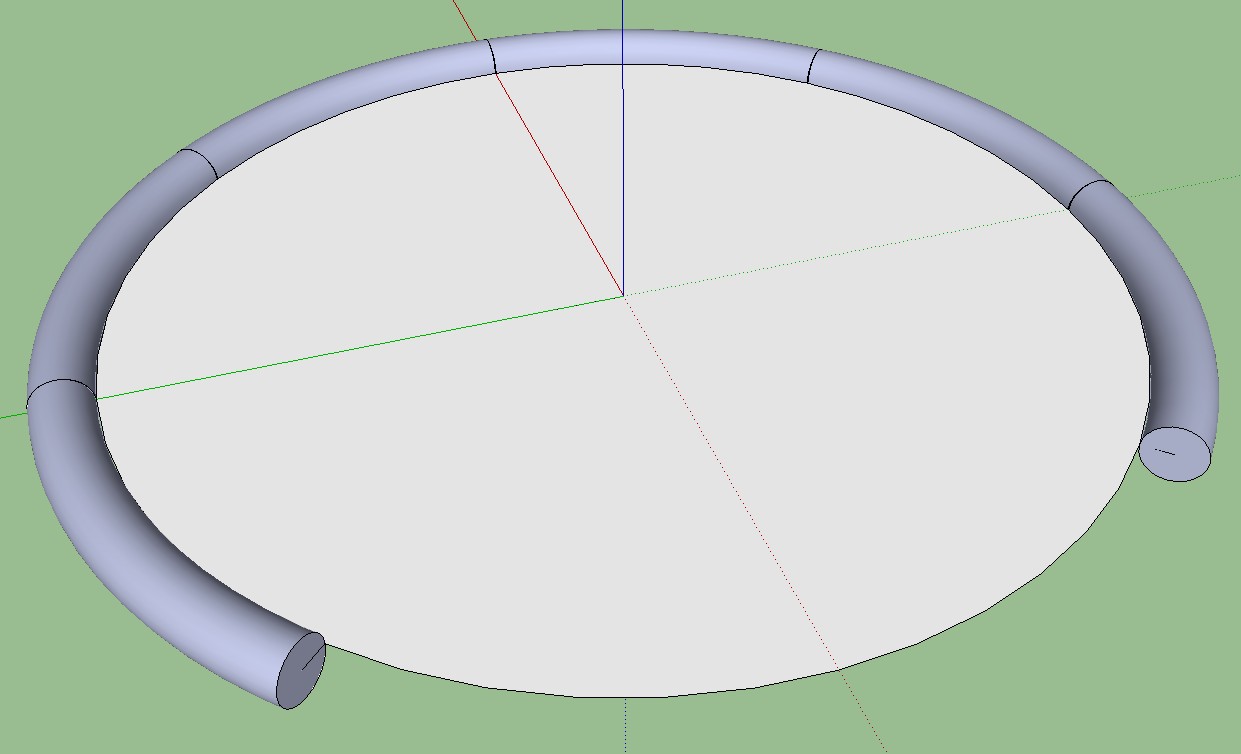
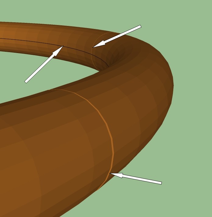
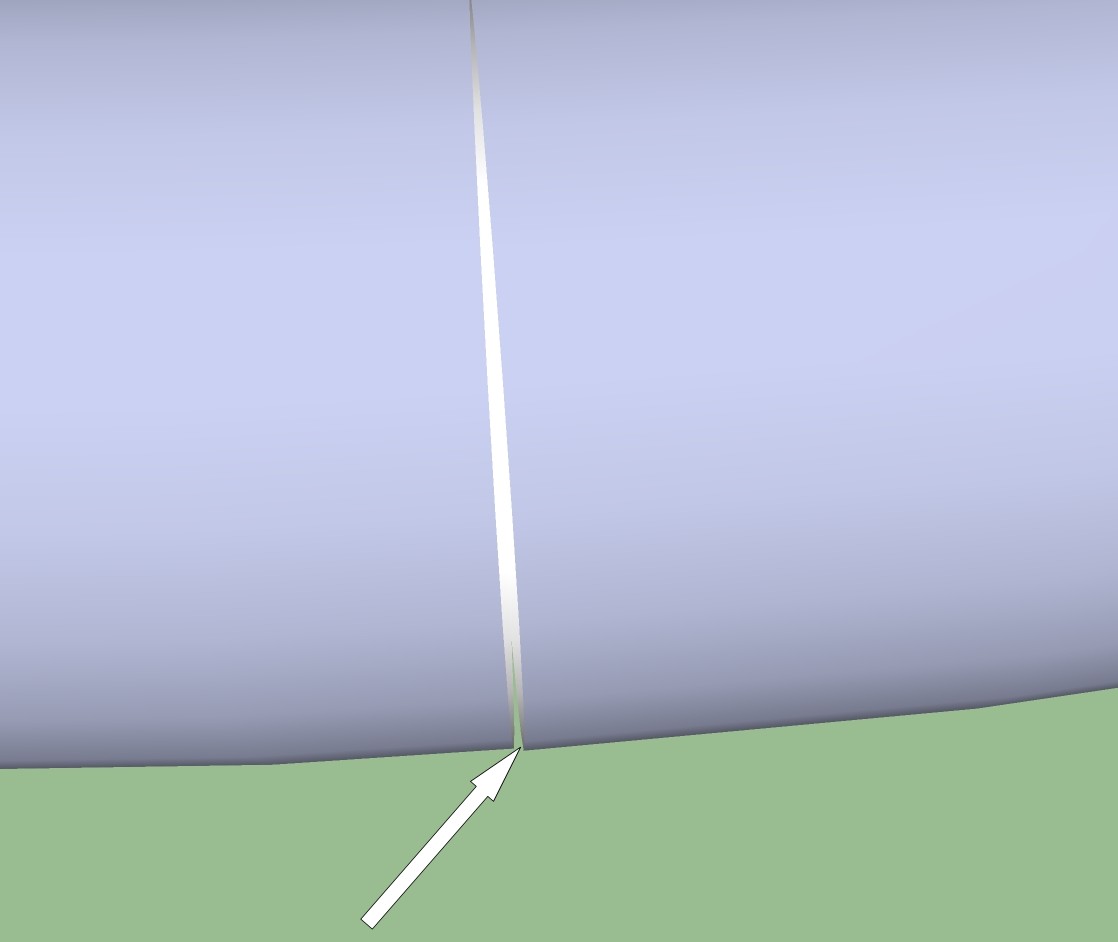
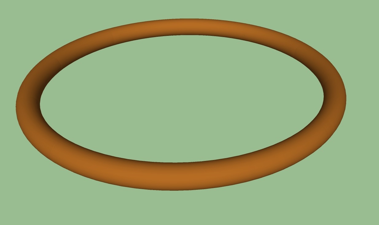
I have been attempting to reduce the size of my model file. I do not like the jagged look of using smaller number of circle segments, and one thing I'm trying is copying and rotating a component around a centerpoint. It works fine, gives me the smooth surface I want and gives me a file less than one quarter the size I would get if creating it normally. The only problem is the lines where the components touch. Also, there is the ring around the inside of the shape that occurs after I delete the disc used to form it. Nothing I do seems to get rid of them entirely, smoothing helps but as you can see by the third photo, they're still noticeable. Any suggestions?
-
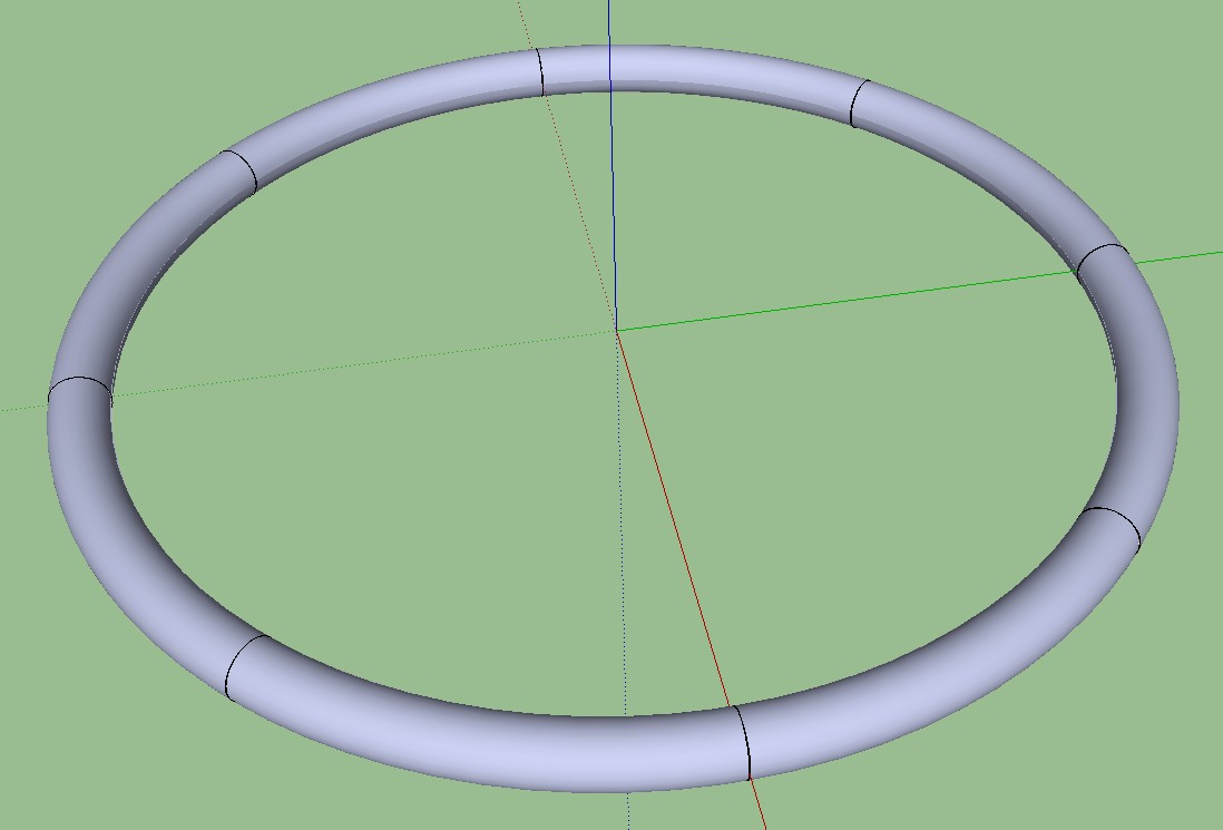
Ok, I've figured out how to get ring of the ring around the middle, but can't do anything with the lines where the components come together.
-
Delete the circular end faces that are hidden when the components join, and hide those edges (shift+eraser or select > rt click > hide)
Jeff beat me...
-
@hellnbak said:
Ok, I've figured out how to get ring of the ring around the middle, but can't do anything with the lines where the components come together.
you have to delete the circular profile faces on the component.
[edit] at least i think you do.. hard to tell from the jpgs alone though..
maybe post the skp if that doesn't work out. -
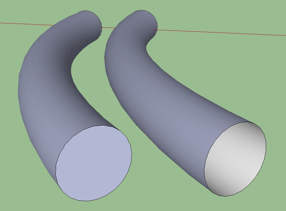
If this is what you mean, I tried that.
-
@d12dozr said:
Delete the circular end faces that are hidden when the components join, and hide those edges (shift+eraser or select > rt click > hide)
Jeff beat me...
I'll try hiding the edges. Thanks
-
Well, hiding the edges helped, but there was still a problem. There was a very small gap where the components joined together. Don't know why. I solved that by just not rotating the parts completely, let them overlap just a bit. Works like a champ. And I miscalculated on the file size - it's actually about 1/7 of what it would have been using the old method. Oh joy, oh joy!


I've always hated those blocky looking circles I plan on putting this to use in a number of ways in the model I'm working on.
You guys are the best!
-
With precise modelling of those parts, that overlap or gap should not happen at all. Something must have gone wrong there I have to say.
-
To get any more precise I would have to get down to the molecular level
 I know it was probably something I did, but I was very careful, or at least as careful as I'm capable of being considering how much sleep I've gotten lately. For now, overlapping them seems to work fine, so I'll settle for that. I'm gradually finding ways to get my file size down to reasonable levels, learning good stuff in the process. This first project of mine is taking forever, but it's just something to learn on. Between the internet, my books and you guys, I have an almost infinite source of help and information to draw from, so I'll get there.
 -
If you make the extrusion of the ring piece from midpoint to midpoint of the circle segments, they will line up precisely. See attached; Scene 1 with one component of the "RingPiece", Scene 2 with the component copied along the circle - no overlaps, gaps or seams visible.
-
Csaba is right. Us a circle instead of an arc for the Follow Me path and split the circle at the midpoints of sides. Then run Follow Me along the resulting arc. Delete the faces on the ends as has been mentioned so when you hide the edges at the ends, you have no seam line.
Follow Me rotates the profile so that it is perpendicular to the first segment in the path. The extrusion ends so that the profile is perpendicular to the last segment in the path.
-
Getting it set up that way would be easy if you're using a low number of segments, you can easily see them and deal with them. But the whole point of me doing this is to use high segment numbers for a smooth finish, and with that many segments it's impossible to tell where one starts and another leaves off. At least with my limited knowledge. Is there a disadvantage to overlapping the components?
-
Segment count should not be an issue here, believe me. As for a disadvantage? Well, maybe other than your own satisfaction, no. But sometimes it can be crucial. If you were to render this stuff in some ray tracing, photorealistic renderer, you could easily get some nasty light leaking effects this way.
-
Here is one for you with 96 segments* (both the circle and the tube). It should be high poly enough (and did not take longer than the first one)
*** I like to use multiples of the default 24 segments. They are easy to divide by a bunch of numbers for precision but of course the segment count should be up to the number you wish to divide it by if ou want to divide at all.**
-
OK, I've figured out how to do that. I'm gonna get some sleep and try it if and when I wake up. Should be sometime in December.
-
Why do you need the high number of segments? Overlaps the components can show as bad as the gaps you have in some cases.
It isn't that difficult to divide a circle at the midpoints of sides. Draw the circle out on axis and rotate it half the angle between vertices on the sides. For a 24-segment circle, the angle between vertices is 15° so you rotate the circle 7.5°. Then you can easily locate the midpoints and draw little line segments to split the circle. Delete the part you don't need.
-
@dave r said:
Draw the circle out on axis and rotate it half the angle between vertices on the sides.
Exactly how I did it (only I did not care for numbers just grabbed a midpoint and rotated the circle to the axis).
After I made the extrusion, I rotated the whole thing back so it aligns to the axes nicely (another useless precision mania?)
-
I use this method frequently for turned legs and such. For example, this turned post is made of eight sectors as shown on the right. The nice thing is that it saves out at about 43 Kb.

Hello! It looks like you're interested in this conversation, but you don't have an account yet.
Getting fed up of having to scroll through the same posts each visit? When you register for an account, you'll always come back to exactly where you were before, and choose to be notified of new replies (either via email, or push notification). You'll also be able to save bookmarks and upvote posts to show your appreciation to other community members.
With your input, this post could be even better 💗
Register Login


Advertisement