2D curve wrap to surface cylinder-best method?
-
Like I said, im not really sure what you're trying to draw. Are you just trying to make a helix around a cylinder? If so, there are a few easy ways to go about doing that.
-
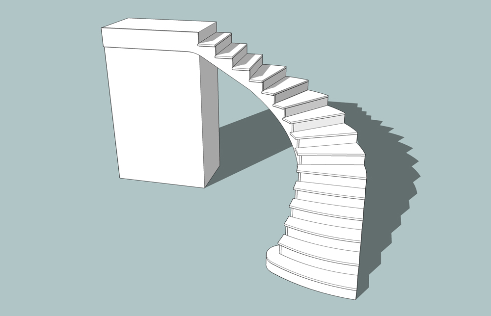
So correct me if I'm wrong but. If we have a set of stairs that has a full rise of say 108", and we want 14 rises it would calculate out yo 7.714". If we decide on a 10" run, then the angle can be calculated to 37.6 degrees.
If we were to draw this stringer out, push pull it through the proper radius of cylinder, and intersect with model(cylinder) would it not project the correct stringer on to the cylinder? Which could be Joint pushpulled to width.
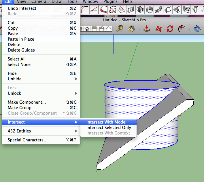
-
Simple helix is not a problem. The issue is creating transitions between helixes of different pitches.
Think of a handrail on a circular stair that does a graceful transition either to level or to a section of the stair that is not pitched the same. The top of the stringer below is usually similarly configured.
Most stair models I've seen here are simple spirals. While portions of some of our circular stairs can be developed as simple spirals, most are more complex and have been very difficult to draw in SU
Attached is a photo/example of one such of transition.

-
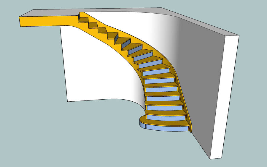
Dale,
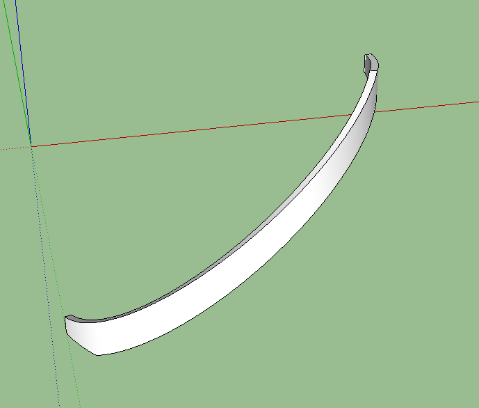
Sorry, but your example doesn't work really. the stringer generated is narrow in the middle and wide (taller) at the top and and ---well, there are a bunch of other issues.I actually use the geometry of cylindric sections often in my work, but re. SU and what I'm trying to accomplish with it,---that's not the answer.
-
@dale said:
If we decide on a 10" run, then the angle can be calculated to 37.6 degrees.
thing is, if you intersect a plane with a cylinder as you've shown, the only place that angle will actually be 37.6 degrees is exactly at the point of perpendicular contact (on a radius line of the cylinder).. everywhere else on the cylinder, the angle will change..
this skp might show the problem better than i can explain with words.
.
-
@volutes54 said:
Simple helix is not a problem. The issue is creating transitions between helixes of different pitches.
that picture helps but just to be clear, when you say 'helixes of different pitches', are you meaning the radius (top view radius) changes..
when i read pitches earlier, i thought you were talking about changes in steepness (as in roof pitches) which was(is) confusing..
i don't think you're building stairs that have a 7" rise for a little bit then they switch to 9", right? -
Of course,
 Thanks.
Are we actually talking about an elliptical helix? -
Actually the pitch may change because there is a transition from straight treads to winders, which shortens the run of the tread relative to the rise (which does stay constant).
And some stairs are nominally "elliptical" in that while their plan may not be described as a true ellipse, one portion will have a broad radius and other sections will have a tight radius.
Jeff, there are many "elliptical" plan stairs in those old Manhattan and Brooklyn brownstones in your area.
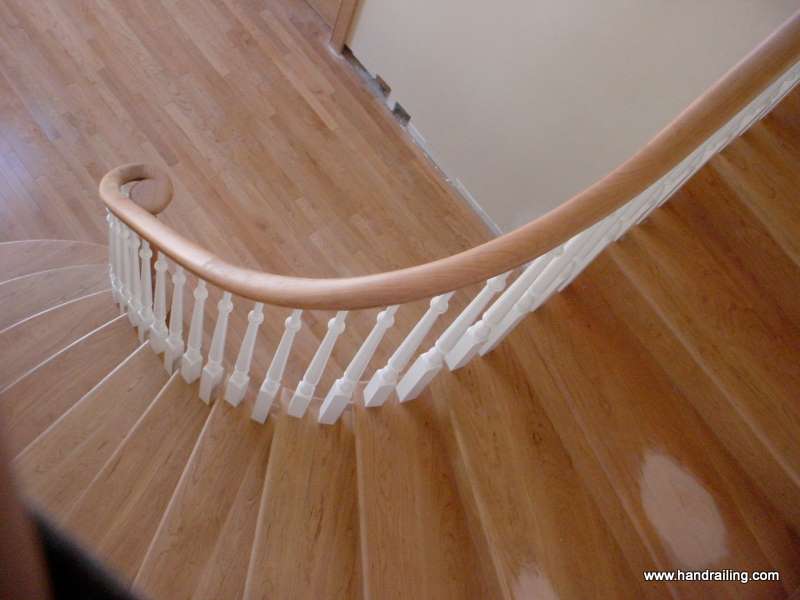
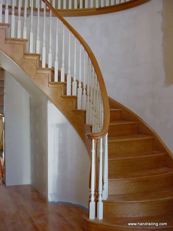
The stringer of the stair shown in the accompanying photos varies in pitch and plan radius. The upper treads are straight and have three baluster. The lower treads are two baluster per--, and the lower end at handrail volute tightens into shorter radius. Yes the upper portion of the stringer is straight in plan, but a smooth transition was made into the steeper curved section. The second photo illustrates the sort of curve that might be developed on a cylindric surface.
-
and another view from the side

-
@volutes54 said:
Actually the pitch may change because there is a transition from straight treads to winders, which shortens the run of the tread relative to the rise (which does stay constant).
And some stairs are nominally "elliptical" in that while their plan may not be described as a true ellipse, one portion will have a broad radius and other sections will have a tight radius.
Jeff, there are many "elliptical" plan stairs in those old Manhattan and Brooklyn brownstones in your area.
The stringer of the stair shown in the accompanying photos varies in pitch and plan radius. The upper treads are straight and have three baluster. The lower treads are two baluster per--, and the lower end at handrail volute tightens into shorter radius. Yes the upper portion of the stringer is straight in plan, but a smooth transition was made into the steeper curved section. The second photo illustrates the sort of curve that might be developed on a cylindric surface.i'm on the top floor of my brownstone (in brooklyn) and have 2 really sweet 100+yr old staircases to navigate every day..
 (probably very similar to what you're trying to draw)
and now that i think of it, a spiral staircase can change pitch simply depending on if you're walking up the inner or outer edge of the thing.
i've gotta get ready to go out but i'll post back later with some ideas.
-
i took a stab at drawing the stairs in your pictures.. i stopped before getting too detailed (no risers, routed edges, railings etc.) but i'm wondering if anything in the drawing is what you're trying to do? if so, i can show you what i did for that part (and actually, once i nearly finished this, i thought up a different method that i could probably do a lot quicker)
i just guessed at the dimensions and tried to get as close to what's happening in the picture as i could see but i think another angle or two would help.. if these are drawn more or less to the proper shape then i would forget about a plugin for drawing a lot of it.. there's just too many weird little things happening in there for a plugin (i think?)i used mostly the line tool and other vanilla sketchup tools for this. (no cylinders though)..
plugins used were:
select curve
weld
extrude edge by vector (this is one that i'm sure you'll find a use for)
a little bit of extrude edges by rails for the bottom of the stringeranyway, i may have found a way to draw them a bit faster but not by much.. (unless it takes you 2+ hrs to draw this much.. then i found a time saver for you)
-
Jeff,
Excellent! The element that I've had trouble with is the stringer ---ie. the side of the stair below the inside radius tread ends. I need to upgrade my SU to v.8 in order examine your model more closely. I'll do that later this today.
-
Like Jeff I couldn't leave this alone,so also tried to replicate from the photo.
The problems I had were similar to ones you mentioned earlier in the Tools on Surface just wanted to make these random lines that seemed to go to some theoretical centre.
When I am doing designs for guitars I have to scale up in order to do some of the work on the neck as it seems to want to leave out some of the triangulation, so you don't get a selectable face. That's what I did here although I still had one line I could not erase without deleting part of the face. I scaled up by a factor of 10, but I think going even bigger would be better.
Used TOS, and Joint Pushpull.
By the way, visited your website, you do some very fine work.
Cheers
-
By the way, here a link to a cool little spreadsheet for helix calculation. It contains cost components as well.
http://www.woodweb.com/software_downloads/formulas_spreadsheet.xls
I really like the springback calculator, and have used it in guitar mold making. There is also a crown molding
calculator and various other nice applications. -
Just checking in quickly.
Dale, I had wondered if scaling up would help out with the Tools On Surface. The specific element I was attempting to draw was a flare in the stringer at the bottom. ---quite small compared to the rest of the stair. ----and exactly the sort of thing that needs to be worked out for the design approval of a client.
I haven't opened Jeff's file since I'm still using SU 7.0 Pro. Is yours in 8.0? I'm reluctant to upgrade because my video card is about about maxed. It looks like you've have good results also. I may see if they have a viewer.
This dialogue has been--and continues to be very helpful. Jeff mentioned he had some additional thoughts on drawing strategy. I'm looking forward them.Thanks for the spreadsheet link (and your compliments on our work)--- I'll definitely check it out.
I'll check in later
Dan B. -
Dale,
re. the springback calculator----- glad to hear it has worked for you, but we've found it's not infallible. -
Dan
Here is the skp 7.. Jeff can probably save his as a skp7 for you as well, his looks a little more elegant than mine.Springback is always challenging. I used to have a lot of fun with curved doors. I think it may be like getting good sound from an acoustic guitar, there's some luck and a little bit of voodoo.
-
here's a step-by-step of how i'd go about drawing these stairs.. (and i'm assuming this might not be much help to you dan as you can probably already draw this stuff and are looking for a more automated method)
i know of some way easier/faster ways to do this if i were just trying to get something to look right but i approached them as if i were going to actually build the set.. (and there are still plenty of things that would need to be drawn or reworked prior to building them.. if i were really going to build this set, i bet i'd end up drawing them 4 more times before i was ready to make sawdust.. with my own work, i can do things first try as i'm way more familiar with what's going on and all of the little nuances etc.)but yeah, i usually draw the more complex stuff i build in a similar manner as shown here.. thing is, i'd rather spend a few extra hours on my computer working through the problems instead of onsite scratching my head and wasting materials.. plus, if you can really draw the stuff accurately, it's much easier to have someone else do all the work while i sit around on site drinking coffee and listening to the ipod
honestly though, sketchup isn't exactly perfect for drawing things like this.. (compound curves etc.) it's ok for single curves and the segmentation can be dealt with rather easily (and in some cases, to your advantage).. it's when you need to bend something then bend it again in a different direction when the headaches come into play.. i've started using rhino lately for the compound bends and really, it's way better/faster/easier/more accurate for this type of stuff.
here's a SU 7 file.. click the scene tabs up top to go through the process..
[i'd definitely be interested in seeing a better way and i'll see if i can come up with something else too]
-
-
Well this has turned out to be a very informative thread.
Jeff are you using Vector Pushpull? I am just using JPP , and attached the file for perusal. The only difference I can see in our methods is I used the inner radiused shape as the stringer surface. In this file I just randomly Joint PushPulled to 4'9 or thereabouts.
However I am not getting the same results(see attached jpeg and skp.) as my rises and runs are maintaining 90 degrees.
I do agree that Rhino (and Blender) probably does a better job and have often wanted to break down and learn it. How is the learning curve by the way?(no pun intended)
I did a little research on JPP, and apparently if the curves get too complex the geometry will intersect itself, which is probably why I have a line I can't delete without removing part of the face.


Hello! It looks like you're interested in this conversation, but you don't have an account yet.
Getting fed up of having to scroll through the same posts each visit? When you register for an account, you'll always come back to exactly where you were before, and choose to be notified of new replies (either via email, or push notification). You'll also be able to save bookmarks and upvote posts to show your appreciation to other community members.
With your input, this post could be even better 💗
Register Login


Advertisement