Export For CAM software
-
Still, there isn't a clear solution for exporting DC options.
-
Since an 'option' is itself an attribute can't you use that to 'filter' the other attributes as needed ?
http://code.google.com/apis/sketchup/docs/tutorial_attrreporting.html -
Maybe I could give You an answer if I know anything about Ruby programing
 Downloaded the book "Automatic SketchUP" and I'm even more confused!

-
Can we recap on the issues under discussion here...
Someone wants a tool that lets you export a selected DC as a 2D DXF - you pick the face to be 'up'.
So the tool needs to find the picked face in the DC and then make a 2D DXF from it ?
Perhaps the DC options are only needed for other reporting and not the DXF making ??
The DXF is made a report is made referencing the DXF and containing certain info extracted from the DC ?Please could the 'requester' post a step-sheet with images, results etc on how this is currently done 'manually' so that the automation is then clearer... I must be readily doable ?

-
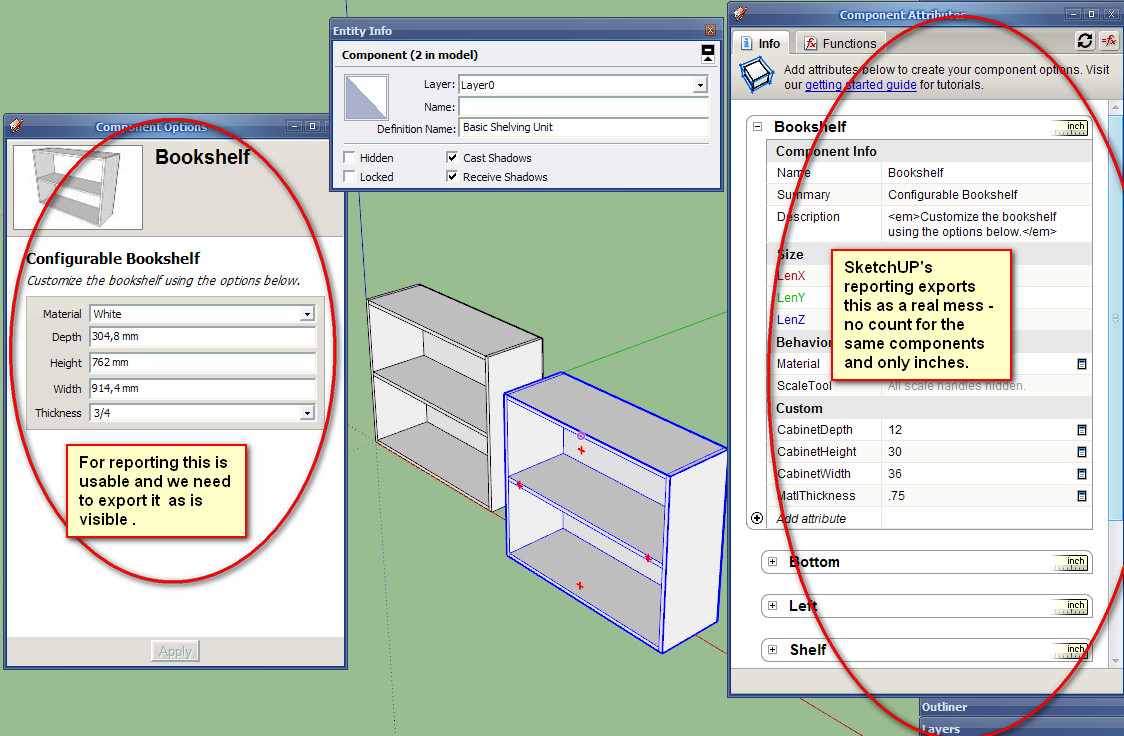
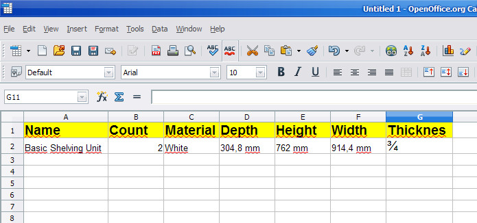
I can comment only on exporting DC options, not attributes! Here we put all the valuable information that is visible and usable in SketchUp and in SketchUp Pro. We can make different components and put the info we need - for legs, doors, panels, handles and etc. that have the same options - we can select all the legs and change their options at once - for instance color or price. Then we need to export all this for reporting - the best as cvs so we can import in Excel or Calc and combine all the elements to get this


-
The the options are the attributes. You need a [new] attribute reader customized to your needs...

-
Does SketchUP holds all the attributes and the options in the same dictionaries? If so then the reader needs to export only the options of the selected components from that table.
-
The instance should hold various attributes values, the dictionary can be named whatever the creator called it - e.g. 'product_info'.
The DC's options/attributes are found in a special 'dynamic_attributes' dictionary.
The code at the end of the link I posted is specifically made to show you how to extract such info from a model / instance etc... -
The geometries should also be exported as follow:
- Create a dynamic component with attributes to be exported in the csv file.

- Select primary face in all components to be machined. (components such as hardware are excluded if no face is selected). Only one face per component can be selected.

- Tooling is set by placing geometries in specific layers. For example vertical drilling with a 5mm bit would be associated with the dxf layer called “DV_5”; Routing offset for external shape with DXF layer “ROX_9” (9 for a 9mm router bit.) any combination of machining can be accomplished by linking tooling “strategies” in the CAM software with DXF layers created by Sketchup.

- When the model is ready all “primary” faces are exported as DXF polylines in a specified folder together with the csv file.

- The csv file is then used to automate the import in the CAM software (Enroute, Aspan etc...)

-
I use a script to export the Entity Information, Attributes, and Outline (BOM Structure) from the SUP drawing into CSV files. But the CSVs are not "flat files", they use the EntityID to link records between each file after they have been imported into a database. I have attached samples of the files, perhaps the Data functions inside OpenOffice can help "flatten" the attribute information? or they could be imported into an OpenOffice Base ".odb" database, then you could write queries? Not sure if OpenOffice can link to the .csv files like MS Access does, and then you wouldn't have to re-import each time? Anyways, the script is very BETA at this point.
-
not sure if this will be of much help. I have used sketchup for CNC work and some of the plugins such as stl or dxf converters are good such as the one here
[url]
http://www.guitar-list.com/.../convert-sketchup-skp-files-dxf-or-stl
[/url]
but i also use mesh lab software. I only use this for smallish models and prototypes so I am not sure how well it will work for you but try itexporting from sketchup as a collada file and them messing about with it in meshlab, it does seem to work but needs experimenting with depending on what you are doing
-
@sketchdata said:
I use a script to export the Entity Information, Attributes, and Outline (BOM Structure) from the SUP drawing into CSV files. But the CSVs are not "flat files", they use the EntityID to link records between each file after they have been imported into a database. I have attached samples of the files, perhaps the Data functions inside OpenOffice can help "flatten" the attribute information? or they could be imported into an OpenOffice Base ".odb" database, then you could write queries? Not sure if OpenOffice can link to the .csv files like MS Access does, and then you wouldn't have to re-import each time? Anyways, the script is very BETA at this point.
Why it is so hard to just export component's options? All this data is so messy - seems easy to me just to write by hand what I need!
-
-
Because, instead of exporting, not seeking to make the process within CAM SketchUp?
In this forum there is an excellent plugim to 2.5D (to generate GCode)
http://www.phlatforum.com/There are already other plugim for developing 3D
-
Here is a video on the SketchUp reporting solution we have been working on.
http://www.youtube.com/watch?v=M2Y53vgqSQs -
Just a sample how simple things can be made complicated! Really scaring!

-
I'm guessing you don't like the reports?
-
@sketchdata said:
I'm guessing you don't like the reports?
In my previous posts I outlined what I thinks is a good use of the dynamic components data. We can put one data for panels, another for hardware and etc. Export this as csv and combine as You wish in Excell or Calc. So far seems impossible to do in SketchUP - and especially if there are non english characters.
Something You can do in CAD with BOM - You can choose what to include in the BOM, have different templates, put custom data and etc. -
I hope I understand your reporting concerns, I think your looking for the following? What if we put the different part types on their own layers, example cut parts on a "CUT PART" layer, Hardware on "HARDWARE" layer, and if all the entities on that layer share the same attributes. Then as the report prints, the rows could be grouped together by layer and the column headers could change to match the attribute names for entities in that group? then export the report to Excel? The non-english issue is interesting, I will see if I can determine language on the client machine, and have the report translate the attribute names.
-
@sketchdata said:
I hope I understand your reporting concerns, I think your looking for the following? What if we put the different part types on their own layers, example cut parts on a "CUT PART" layer, Hardware on "HARDWARE" layer, and if all the entities on that layer share the same attributes. Then as the report prints, the rows could be grouped together by layer and the column headers could change to match the attribute names for entities in that group? then export the report to Excel? The non-english issue is interesting, I will see if I can determine language on the client machine, and have the report translate the attribute names.
Yes, that is exactly my point! Because the info that one needs is different for different parts. For example - for the purchased legs we need the supplayer, the material(color),the price and maybe the height of the legs. And the attributes gives Us the freedom to put this data, but so far there is no way to use it for reporting. And even there is no need to export all at once - just the parts with identical attributes - and then we can put this data on a separate sheets or in the same sheet and etc. This also works with the free version - the supplayer puts the attributes that the customer can see and fill and then can send back as an order.
Advertisement


