Export For CAM software
-
Because, instead of exporting, not seeking to make the process within CAM SketchUp?
In this forum there is an excellent plugim to 2.5D (to generate GCode)
http://www.phlatforum.com/There are already other plugim for developing 3D
-
Here is a video on the SketchUp reporting solution we have been working on.
http://www.youtube.com/watch?v=M2Y53vgqSQs -
Just a sample how simple things can be made complicated! Really scaring!

-
I'm guessing you don't like the reports?
-
@sketchdata said:
I'm guessing you don't like the reports?
In my previous posts I outlined what I thinks is a good use of the dynamic components data. We can put one data for panels, another for hardware and etc. Export this as csv and combine as You wish in Excell or Calc. So far seems impossible to do in SketchUP - and especially if there are non english characters.
Something You can do in CAD with BOM - You can choose what to include in the BOM, have different templates, put custom data and etc. -
I hope I understand your reporting concerns, I think your looking for the following? What if we put the different part types on their own layers, example cut parts on a "CUT PART" layer, Hardware on "HARDWARE" layer, and if all the entities on that layer share the same attributes. Then as the report prints, the rows could be grouped together by layer and the column headers could change to match the attribute names for entities in that group? then export the report to Excel? The non-english issue is interesting, I will see if I can determine language on the client machine, and have the report translate the attribute names.
-
@sketchdata said:
I hope I understand your reporting concerns, I think your looking for the following? What if we put the different part types on their own layers, example cut parts on a "CUT PART" layer, Hardware on "HARDWARE" layer, and if all the entities on that layer share the same attributes. Then as the report prints, the rows could be grouped together by layer and the column headers could change to match the attribute names for entities in that group? then export the report to Excel? The non-english issue is interesting, I will see if I can determine language on the client machine, and have the report translate the attribute names.
Yes, that is exactly my point! Because the info that one needs is different for different parts. For example - for the purchased legs we need the supplayer, the material(color),the price and maybe the height of the legs. And the attributes gives Us the freedom to put this data, but so far there is no way to use it for reporting. And even there is no need to export all at once - just the parts with identical attributes - and then we can put this data on a separate sheets or in the same sheet and etc. This also works with the free version - the supplayer puts the attributes that the customer can see and fill and then can send back as an order.
-
I will work up a report that groups/totals like parts based on their dynamic attributes, and then the report can be exported to Excel. Since SketchUp stores the measurements in Inches, we had to add a conversion to the Model Units (mm, fraction, decimal) when displaying the data on the reports. I'm still thinking about the Language conversion issue, we need to convert the column headers and the attribute names to your local language? Do the attribute values need to be converted too? What language would you like it converted to if I can produce a sample spreadsheet?
-
These are sample files. A SketchUP's component with name and attributes in Bulgarian language and Excell table from this attributes.
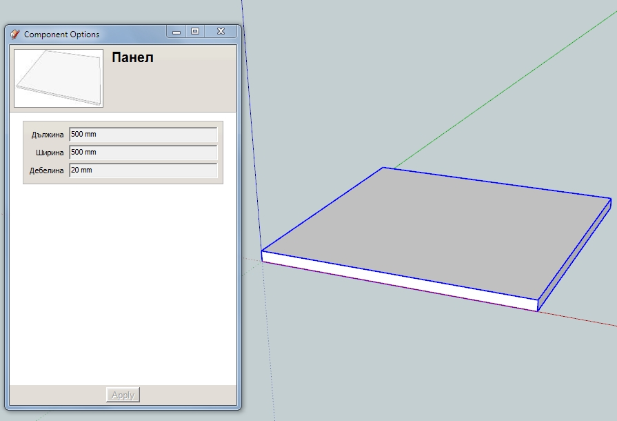
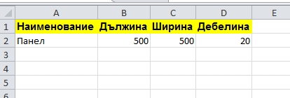
I don't know,but seems that SketchUP recognizes different languages in attributes and correctly displays them.
-
When I open up the "Component Options" dialog in my SketchUp I still see the Bulgarian, but when I open the "Component Attributes" I see English LenX,LenY,LenZ. So I created a report to group and sum qty on components that have the exact same attribute values and then used the "Display Label" as the column header, which is not the internal attribute name, but the name that displays on the "Component Options" dialog. I attached a sample SKP which has copies of your part with different sizes so I could test the report quantity column, also attached is a PDF and Excel file of the report. Please let me know if this helps, or if I'm way off. Thanks...
-
Yes, that is! SketchUP doesn't allow non English characters for attributes, but no problems with attributes labels - and that visible information is really valuable for the report - what You see is what You want on the report! Not how it is with the generate report - a bunch of useless information! This way You really control what info and how to export! Thanks!
-
interesting subject.
keep me posted, what about French accents ? !
keep up the good work
-
Numerous progs have some trouble with accents!

In the path's folders, files'names or even in the prog it self!For example Zbrush can't have a French Interface due the French accents!

Because it was not managed from the beginning, now it's to late!So don't take names files or path folder with accent when you write in French

-
@dedmin said:
Fully agree with You!! I wonder why nobody did this already - there are so many fellow woodworkers ready to pay for this!! But when You export a 5mm circle from SketchUP as .dxf it is not a circle anymore - that is why I asked above if this is a problem with CAM?
What it could is when exported convert all circles to a high segment polygon,via a input box
Ie a circle that has 10 edges could be converted to a circle with 100 edges giving the appearance of a more precise circle
depending on the tolerance of a hole. and insert a cross hair in the centre to denote the centre of the circle of a standardised size say 5x5mm or an input box could include this feature to choose.This then could have an option to convert all holes in model , voila problem sorted
obviously this would only work on flattened geometry for export to 2d cad cutting , say laser cutting
What do you think?
Thanks
Paul
-
Sorry, but I don't have experience with CAM and CNC. Maybe somebody else can answer - I'm also interested in this. Waiting for a long time somebody to take SketchUP more seriously in this area and develop the needed tools and plugins.
-
Hi,
Exporting faces using the native Sketchup pro dxf export will create true dxf arcs and circles.
When I export bezier curves or splines Sketchup creates segmented dxf shapes. This is not a problem as increasing the number of segments will create the illusion of a smooth curve.Regards,
Yvan -
@paulhankin said:
@dedmin said:
Fully agree with You!! I wonder why nobody did this already - there are so many fellow woodworkers ready to pay for this!! But when You export a 5mm circle from SketchUP as .dxf it is not a circle anymore - that is why I asked above if this is a problem with CAM?
What it could is when exported convert all circles to a high segment polygon,via a input box
Ie a circle that has 10 edges could be converted to a circle with 100 edges giving the appearance of a more precise circle
depending on the tolerance of a hole. and insert a cross hair in the centre to denote the centre of the circle of a standardised size say 5x5mm or an input box could include this feature to choose.This then could have an option to convert all holes in model , voila problem sorted
obviously this would only work on flattened geometry for export to 2d cad cutting , say laser cutting
What do you think?
Thanks
Paul
You can always increase the circle segment size to get better circles. But gcode also does circular interprolation (G02 and G03). One is for clockwise and the other couter clockwise. You just need to supply the end points of the segment and the radius or center. The phlatscript sketchup plugin makes some use of this. For example a 3 segment circle and the simulated gcode, pictured below. I don't know if my eye is playing tricks or not, but it looks just a fraction off. Possibly round off error. But this is an extreme case. With a few more segments it looks perfect. Certainly, a 8 segment circle looks perfect.

-
@yvan said:
The geometries should also be exported as follow:
- Create a dynamic component with attributes to be exported in the csv file.

- Select primary face in all components to be machined. (components such as hardware are excluded if no face is selected). Only one face per component can be selected.

- Tooling is set by placing geometries in specific layers. For example vertical drilling with a 5mm bit would be associated with the dxf layer called “DV_5”; Routing offset for external shape with DXF layer “ROX_9” (9 for a 9mm router bit.) any combination of machining can be accomplished by linking tooling “strategies” in the CAM software with DXF layers created by Sketchup.

- When the model is ready all “primary” faces are exported as DXF polylines in a specified folder together with the csv file.

- The csv file is then used to automate the import in the CAM software (Enroute, Aspan etc...)

this is very interesting and this process is exactly what i have been looking for?
i need to be able to select a face of a cabinet, automatically apply the shelf drilling & hinge boring.
export this as a flat dxf, i have been doing this with a section slice and opening this is in autocad to set
requirements for cam but the dxf from sketchup comes through with broken segmented lines so i use
the dxf to trace. can anyone help with this??
Hello! It looks like you're interested in this conversation, but you don't have an account yet.
Getting fed up of having to scroll through the same posts each visit? When you register for an account, you'll always come back to exactly where you were before, and choose to be notified of new replies (either via email, or push notification). You'll also be able to save bookmarks and upvote posts to show your appreciation to other community members.
With your input, this post could be even better 💗
Register Login


Advertisement