Punching holes please
-
Tig,
Thank you for the reply. I made a test hole component. I chose glue to any and checked off cut opening. I made hole exactly as shown. Then I made a rectangled box. Did the same . Can't get it to work. I exploded the box, still no go.Is the box supposed to be a componenet at this point ? Even an exploded box shows one face which covers hole. Hole shows only as a circle on surface of box. Like I said, I'm feeling really dense on this one. -
A cutting component will only cut a hole when it is placed directly onto a face - my skp tut' has the 'box' faces as "raw geometry", one taking the 'hole' component.
If the face that's to take the hole cutting component is inside a group or component then you must edit that group/component so that the 'hole' is added directly onto a face within the group/component. If you apply a hole cutting component onto a face that is actually nested inside a group/component then, as you have found, it snaps to the surface BUT it won't cut a hole because the cutting component and the face are in different 'entities' sets - in the same way that geometry inside a group or component no longer sticks to other 'external' geometry or to other groups/instances...
Placing the hole-cutters onto a face that is actually inside a component/group and then exploding that will put all of the geometry and hole-cutters into the same entities set, BUT they won't cut holes in a face because a hole-cutter component only cuts a hole of the face it is placed onto initially - i.e. as it is added to the model, not later on. There are 'reglue' plugins that let you select some hole-cutting instances and one face and then the hole-cutters are relinked to that face, so holes then do get cut... BUT at this stage you are trying to learn the basics of adding hole-cutting components - so please put your hole-cutting components directly onto faces initially - remember to edit a group/instance you can simply double-click on it, so that you are then working inside it... You should keep the 'reglue' plugin possibilities in the back of your mind - it could be useful if for example you have a facade and its main face gets accidentally deleted and later you notice that dozens of windows that you had carefully placed no longer cut their holes, even when you recreate the facade face - THEN you could use 'reglue' to fix it - but it's for the exception rather than the rule...Hope this helps...

-
Thanks again for the lengthy reply. What you reiterated is my understanding ( I think) of the process. Here's a test I just did and as you can see the component ( the hole, with cutting checked) is partly inside of raw geometry and is not cutting thru. Moving it all the way in changes nothing. Is it possible that I have a preference somewhere set wrong ?hole test.skp
-
Moving an already placed cutting-component between entities-sets will not make it cut something - just the same as exploding the host of the face won't work...
Please just add the cutting-components to a face that's in the same 'edit-session' - i.e. they are both in the model, OR both inside the same group/component edit-session.
Once you have placed a cutting-component you cannot change what it is set to cut [unless you use a 'reglue' tool].
Placing a cutting-component onto a face that's inside a group/component whilst you are 'outside' of it, is the same as placing it in empty space - i.e. it initially has no 'face to cut' assigned to it.
No amount of trying on your part will then make it cut something later on - it's been set to 'none' initially and it simply won't change [unless you use 'reglue'].
Similarly you can't just take a component off one face and move it onto another, even in the same entities-set, and expect it to cut a hole - it'll remember which face it'd been given to cut when it was first placed and that's that! ... [again, unless you use 'reglue'].
Please, try to do it the 'proper' way as explained - you seem to be making it more complicated that it needs to be It is quite simple really...
 -
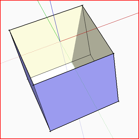
I also note that is your SKP example you have made your cutting-component so that its 'bottom' is at z=0, surely you want its 'top' at z=0 so that it cuts into the face - as it is it simply glues onto the face and sticks outwards, and although it does cut a hole that hole is invisible since it has a circular 'base' over it. Move your component's axes up to the 'open' part of the hole-cutter and retry inserting a new one.
I also note that your hole-cutter has its faces made 'inside-out' - it's not a cylinder, it's a 'hole' - so select the side and right-click > context-menu > Reverse - also repeat that for the 'base' face - so that then any face and its cutting-components will have faces with the same orientation...
-
Sorry TIG, I'm trying. On my example I placed a cicle exactly over the axis as I understood it from your example, then pulled it downward which I assumed meant that the face is now in the z=0 position. So are you saying to make the box first as a component/group, then enter edit and create a hole/component in situ,rather than move hole/component from outside ? I still can't get it to work that way.
-
When you make any shape into a component SUp places the axes at the lowest x/y/z location - you don't normally want them there for a cutting component - unless you have made it upside down

 You can set a component's axes in the create dialog
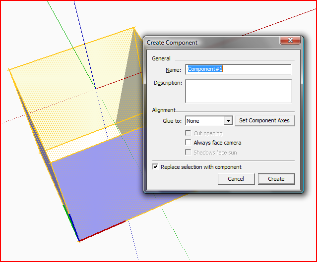 thus
thus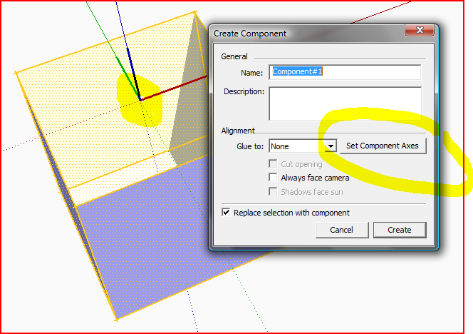
Don't worry about making the face's box a group or component - leave it as raw geometry and place your hole-components onto it - they should cut if you set its properties right [note that these are yet to be set in the last image above - Glue>Any-Face, tick=Cut-Opening]...
IF you have some faces onto which you'd like to add hole-components BUT these faces are inside a group/component then edit the group/component until you are at a level where you can select the face on its own - then you know it'll take components and that they'll 'glue' and therefore also 'cut' successfully... -
OK, I made a circle, pulled it up, deleted both top and bottom faces, set the axis as shown on the top of hole with blue going up, created component with glue to any and cut opening checked. Then made box without making component. Then with move tool I moved hole component over box and it will not cut. I rotated it upside down and tried again.I really have got to get this. I've been doing well with the program execpt for this one thing. I know if I can get this I'll understand a lot more than just hole punching. Thanks for your patience.
-
I said before... you cannot 'move' a component onto a face that it wasn't originally placed on and then expect it to cut a hole. The 'original' component is set to cut-face='none' as it was made 'in space'...
Place a new version of the 'hole' component by inserting it from the Component Browser window - it should now cut a hole in the face... You can copy a hole that is already on a face and the copy will cut it - as a copy will 'find' the face it first 'alighted' on and so it will cut it... -
Hi Otis,
Try this way;
- create a box (on which you will place the components).
- draw a circle on a face of this box
- double click on this circle (so that its face and the perimeter is selected)
- right click on the selection > make component.
- Now notice that the gluing plane is already set and also it is set to cut a hole by default in SU.
- Now double click on your newly created component (to edit it) and PushPull its circle face down to the distance of the bow you placed it onto. (You cannot really see anything at this point)
- finally erase the top circle face which is still there as you have just made a tube with both beginning and ending ends filled.
- Now exit your component and try to place a new instance from the component browser to see if you made it correctly.
-
Thanks Gaieus, it was the order of the thing that had me flumaxed. It works perfect now. Also many thanks to TIG, your patience knows no bounds.
-
As TIG pointed out above, you were probably doing it "half" correctly already - only the gluing plane was somehow reversed and you components were gluing upside down.
To be honest, out of laziness and to make it fool proof for myself, I regularly make my gluing/cutting components in the way I outlined above. As such "flat", 2D components created on a face are automatically set to glue and cut hole in SU, that's the best way to make them without error.
-
-
Hello Tig,
It's not very intuitive the way it works now, I must say. It seems to be something simple that SU can improve on.
It should be as simple as:
1)you draw cut shape in xy plan and give depth in z direction.
2)tell it to which cut plane or all.
3)locate on desired surface.
4)should be able to copy paste component to any other surface in any skp file without losing its cutting properties.
If it doesn't work this way what advantage is gained for cutting holes when you can do this already without making it a component.
-
Currently that's why 'reglue' tools exist...
Hello! It looks like you're interested in this conversation, but you don't have an account yet.
Getting fed up of having to scroll through the same posts each visit? When you register for an account, you'll always come back to exactly where you were before, and choose to be notified of new replies (either via email, or push notification). You'll also be able to save bookmarks and upvote posts to show your appreciation to other community members.
With your input, this post could be even better 💗
Register Login


Advertisement