Help Me Draw A Dome [TUTORIAL]
-
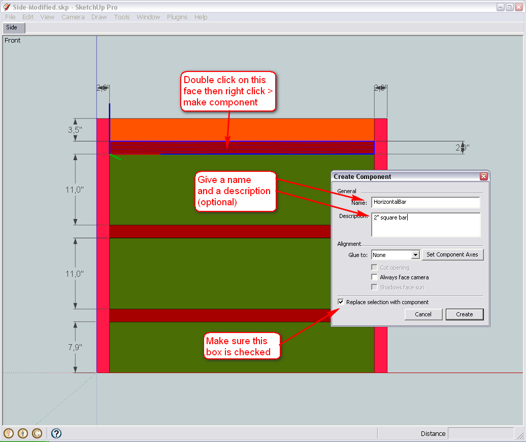
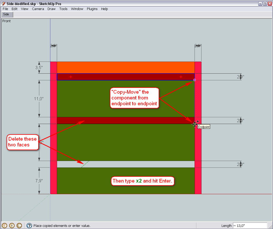
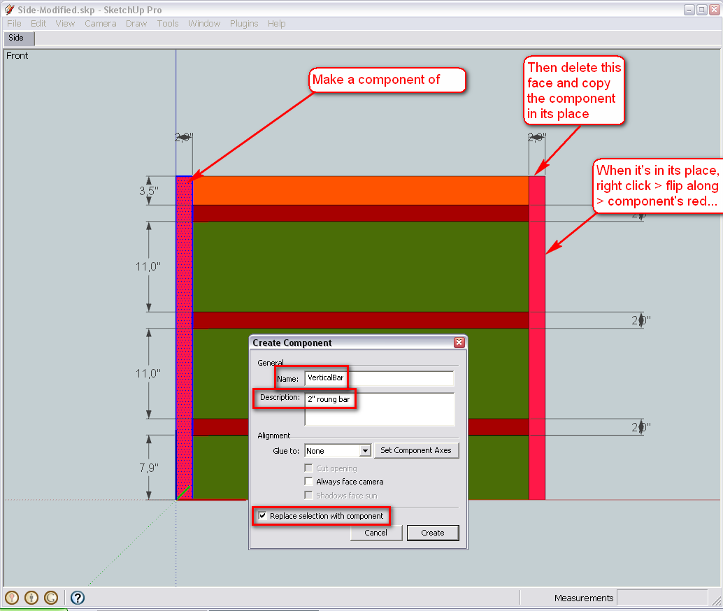
Sure - I will go back a bit and modify our "side" component with the appropriate steps. So is the diameter going to be 2" then?
-
Hi Gai
Yes, 2" is fine.
Regards
D0me -
Okay, let's see then.
First we get rid of the dimension lines (if we do not need them any more - otherwise just turn their visibility off under the View menu). So enter the "Side" component (double click), go to Window > Model info > Dimensions, select all dimensions and delete them.
Now outside of everything, draw a circle with a radius of 1" (this will give a diameter of 2"). Make sure to pull its radius out along either the green or red (like in the picture) axis. Also, remember that until now, we have always set some bigger segment count to circles and arcs but we do not need to do this in this case as these legs will not be so prominent in our model so the default 24 segments will just do fine.
When we are drawing looking down (to get a blue circle), it is drawn on the ground plane (defined by the red/green axes) by default. In our model, it is at the top of the base structure so we will need to PushPull the circle downwards.
To make sure it won't get "sticky" to other geometry while we are positioning it, select all of our cylinder (triple click), right click and make it a group.
Now simply copy it with the default, Windows copy shortcut key (Ctrl+C), enter entirely into the component of the leg and paste in place for the time being (this is in the Edit menu but as far as I remember, you already have this as a custom shortcut: Shift+Ctrl+V)
Note that we do no really need it here, so a simple paste would do (Ctrl+V) but then we immediately need to position it)
Now select the Move tool find the endpoint that is pointing the farthest to "south" (along the green axis) in the group, grab the group at this endpoint and move it to the midpoint of the face in our component.
Now double )or even triple) click on our "old face" and delete it as we do not need it any more.
You can also explode the group - its geometry will now replace that of our old leg component (in both instances in the model)
After exiting the component, this is what you are supposed to see. Not perfect yet (the round leg affected how the other components look in relation to it) but we will handle that later.
Delete our temporary cylinder group.
Here is the model how I have finished it - for a reference (I think the biggest issues with mistakes and such come from all these different versions and when we incidentally mess up whcich one to go on working wioth )
-
Hi Gaieus
I've done the following but was unable to proceed further after my point number 5.
- I drew the circle along the red axis.
- I pulled the circle downwards and snapped it to my right square bar that is currently there and the tool tip "Endpoint" appeared
- I made the newly created cylinder a group by triple clicking.
- I then clicked the cylinder once and pressed ctrl+c
- I then double clicked the side group to get inside of it and then I double clicked the square bar (leg). I then went to Edit > Paste In Place. I now notice a bar on my left side that's also created.
I've cant seem to proceed any further.
Every time I try to move the cylinder to the midpoint of the leg, it somehow dosent snap to it or offsets the side piece completely. I've been at this since last night but just cant seem to get any further . Please tell if so far I'm on the right track as knowing me, I probably did something wrong when creating the cylinders and that's the reason i cant get any further.Thanks
-
@d0me said:
- I then double clicked the side group to get inside of it and then I double clicked the square bar (leg). I then went to Edit > Paste In Place. I now notice a bar on my left side that's also created.
That is good - it means that you succeeded to paste the group into the component itself - and since we have two instances of the same component, and editing one will change the other one, too (that's actually the point here).
Okay, now we will make our jobs a bit easier. Let's start using guide lines (that's what they are for - when you have complex geometry around, you pre-define paths, distances etc with the ape measure tool : - just click on one then the other point with it...)
Here (beside moving the group a bit closer for better screenshots), I established a guide line between the endpoint we need in the group and the midpoint of the face we want to move the group to:
Now if we start moving the group, we can easily get an "On line" inference - and that is exactly the direction we want to do it:
If you now press the Shift key (and until you keep it pressed), the operation will be locked on this direction - you can even move the cursor away - the thick dotted line indicates the direction of move:
Now either without the Shift key, snap the move to the "Intersection" (of the Midpoint and the Guide line):
Or while the Shift key is still pressed, get a "Constrained on line" intersection at the Midpoint (notice that in this case, as far as the "sensitivity" of the inference engine allows, you can even move the cursor away a bit from this midpoint):
Here is the file at its state of the first image - so try to practise all the steps above from that point.
-
Hi Gaieus
I have to be honest and say this was the first time during this entire tutorial that I became frustrated to the point of quitting but you have really been patient enough to provide alternate solutions to every problem I've encountered. A true teacher indeed.So far this is what I've done.
- I double clicked the side group to get inside of it.
- I then double clicked again to get inside of the cylinder and leg group
- Using the tape measure tool, I managed to find the endpoint on the cylinder and drew a guideline to the midpoint of the leg. A note at this point: It didn't say midpoint but a measurement appeared with a blue dot that normally appears when its at the midpoint. I assume that this is correct and the reason it didn't show "Midpoint" is because of using the tape measure tool.
- I then used the move tool and hovered over the cylinder until i got a inference saying "Online Outside Active"
- I then moved the cylinder to the leg until i got a inference saying "Intersection".
- I then clicked on the face of the leg that was there and deleted it.
- Lastly I double clicked the side to get back into the group and then double clicked the cylindrical face, right clicked and selected explode
So far everything looks right but you'll be able to tell me whether its right in terms of geometry.
-
Okay, glad you finally got it.
To tell the truth, first I planned to do it differently but ran into something that (I believe) is a bug. I don't want to go into the details now (maybe we'll discuss it in the Bug Reports subforum once I'll have fully gone around to explore) but definitely did not want to drive you into this bug at this stage.
Also, we could have exported the whole side component ("Save as..." method) and then reload later - but we have done it already so I wanted to do it differently.
Anyway, you seem to have done it perfectly so far.
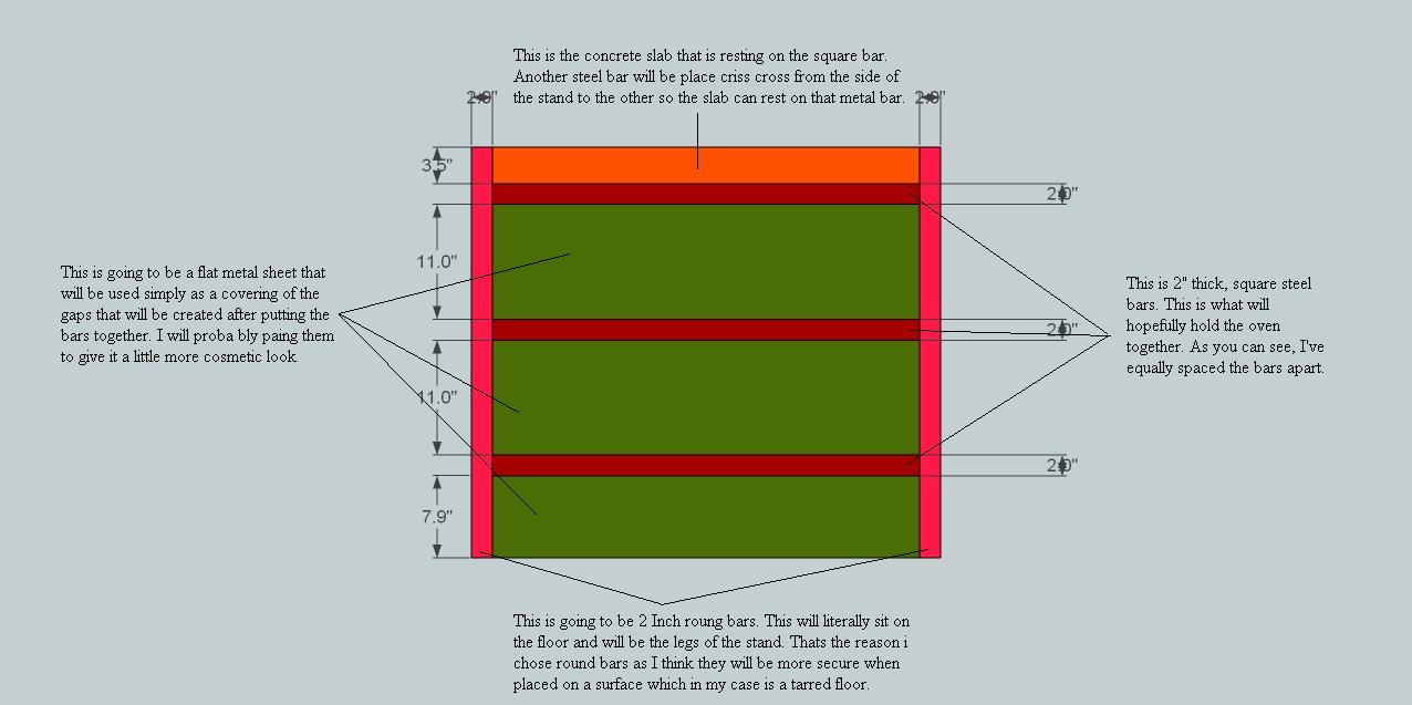
Now we are at a point however where this last modification brings up some questions. What to do with those gaps, how thick those horizontal, rectangular bars should be, where exactly the round legs should be in relation to them and also the siding panels...
So now we make some preparations in order to be able to work easier in the model (without the export/reload function). Let's make a temporary layer where we simply hide everything that is not needed now. Open the Layers dialog from the Window menu and add a new layer with the + sign.
Then select all in the model (not only SU shortcut but Windows in general: Ctrl+A).
Now "deselect" the component we want to work with. Use the select tool (by default, the shortcut is the Space bar). Test the different modification keys:- Shift + = add/remove; indicated by a +/- sign
When using this, clicking on something will toggle its selected/deselected state. - Ctril + = Add to selection; indicated by a + sign only.
Use this when you are sure you only want to add anything you click on (and not deselect something incidentally) - Shift+Ctrl + = deselect (remove from selection); marked by a - sign.
So after making sure that everything BUT the side component is selected, right click the selection, go to Entity info from the context menu and assign this layer to the selection. Then turn off the visibility of the layer so that we can work easier.
%(#BF0000)[Note however that we have done something you should never do - put "raw" (i.e. not grouped or "componented" geometry other than Layer0) and this is a very bad practice - never do that. Always group everything you want to put on a different layer and only "move" the geometry there.
Now we could only do it because we are going to delete this layer later and on that occasion, will move everything back to the default layer..]Well, and now the question you have to think about - how thick should those side bars be? Here I edited one and PushPulled it to the exact thickness of the round leg - i.e. 2" - but this is just for the demonstration (also notice that the other three became modified as well).
- Shift + = add/remove; indicated by a +/- sign
-
Hi Gai
I have added the rest of the model to the new layer and hid everything except the side.
I have also pulled out the square bar by 2" and 2" is fine.
The round legs should touch the square bar as in reality it will be welded to each other. The side covering can be pushed back slightly so it sits flush against the inside of the round legs which is the same spot where the ends of the square bars touch onto the round legs and this should indirectly take care of the gaps.
Can we create scenes for the side coverings so I can choose to display or not display it?
Lastly I notice that underneath the stand, there is a covering. Can this covering be moved up to touch the last horizontal bar?Thanks
-
Okay then, let's go on...
Open a side bar component again and PushPull its end till the middle of the round leg. This endpoint will be the farthest extreme from its midpoint along the red axis - you can play with snapping but knowing that the radius is 1", just type 1" and hit Enter.
The same on the other end...And now let's move the side panels in: selet all three (like above), pick the Move tool and press the left arrow key on your keyboard. This will lock the Move along the green axis (the righ arrow locks along the red and either the up or down arrow along the blue axis). Of course, we could do this with the Shift key, too, but when moving along an axis, this is even easier (some "old" Pro users still do not use this function - at least as often - because it was first introduced in the Free version of SU 5 back almost 4 years ago... )
Start moving and again - either use the snap function or simply type 1" and hit Enter.
So this is what we have ended up and can now see that we have some leftover geometry in our leg component - but we can deal with that later (and maybe it will even serve well as something we can snap to).@d0me said:
Can we create scenes for the side coverings so I can choose to display or not display it?
Sure. Right click on the scene tab and "Add..." (notice that if you "left click" on it - i.e. select it as active tab, it will unhide our hidden layer).
@d0me said:
Lastly I notice that underneath the stand, there is a covering. Can this covering be moved up to touch the last horizontal bar?
We can do whatever we want - but can also leave it there for now. Let's leave it to the end (we will need to adjust the top piece now as well - it will have to be 1" smaller all around!)
-
-
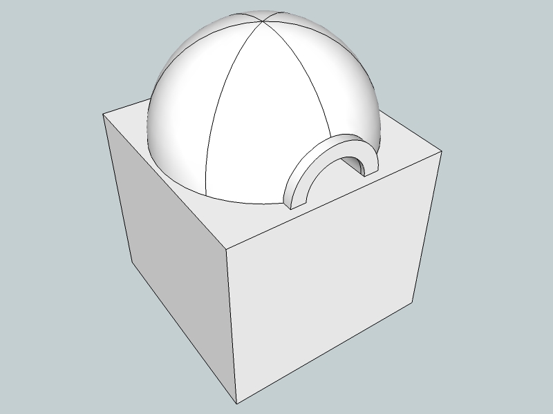
Is it for a DOme version of this?
-
Hi Chris
You've nailed it.
I was actually gonna have the community guess this once complete with the Dome but you've hit it on the head. Well Done.Regards
D0me -
@d0me said:
Hi Chris
You've nailed it.
I was actually gonna have the community guess this once complete with the Dome but you've hit it on the head. Well Done.Regards
D0me... then the door opening needs to be bigger for a reason that I cannot remember - but I got the formula for the one I made from searching the net - about five years ago.
Good cooking!
-
Okay, so it seems that we have only to copy the side component (flipped or mirrored) onto the other side. Of course, we need to know "where", so turn our hidden layer on.
So select the component and copy it onto the clipboard (this copy will stay there until the last step below).Then right click on the component and flip it along its Green axis (we can tell which that is because we have component axis display on - also, after flipping you will see the blue back faces of the side panels displayed out and if we flipped along the red, you could not).
Now it comes handy that we left that "leftover" geometry in the component as it is easy to grab it by that, move the component along the green axis and simply snap this corner of the leftover geometry to the endpoint corner of our base on the other side.
When done, use the "Paste in place" command (Edit menu - or for you, already the Shift+Ctrl+V shortcut command) to get our original component (we copied to the clipboard two steps above) back into its place.In case you had forgotten to make this copy (or forgot that you have it on your clipboard and copied something else and that "occupies" your clipboard now), there is an easy trick you can also try:
- Use the Ctrl+Z key (twice) to undo the move step andto undo the flip step.
- Now make your copy
- Use the Ctrl+Y key (twice again) to redo the flip step andto redo the move step.
- Now Paste in place...
Since undo and redo do not affect what is on the clipboard (that is not SU but the operating system clipboard), it is still there and now you can paste in place.
-
Chris, are you talking about the door width or the height?
Btw, how is the one you built holding up?
-
@d0me said:
Chris, are you talking about the door width or the height?
Btw, how is the one you built holding up?
I think it was the height that was more critical (perhaps for combustion) but the width is important if you want to make "classic" 300 mm diameter pizzas.
Yes it is fine but I encased it with brick walls and granite paving slabs (recycled) as we experience torrential rain in typhoons around these parts. I put the sketches and pics on an old remote hard drive; will see if I can recover them.
-
Hehe... While posting my last part (and kept "previewing" it), I missed Chris' posts.
Well, indeed, with the "entrance" part we already had the discussion about the size above (when we gave thickness to it and all). As the construction of the dome now is, it will allow easy modification (redoing) of that part however...
-
Hi Gai
That part was easy. Saved me the trouble of redoing the opposite end.
So now that leaves the back and front of the stand.
-
Okay but it is decision time again.
If I copy the side component along the red axis...
Then rotate it to form the back side...
It turns out that our sides are longer than the back. This is of course due to the somewhat bigger space we left for the entrance. Now we have two choices:- to make these back pieces unique - this way we lose the advantage to edit the components "at once" when making changes - and also maybe you lose the advantage to "order" a number of exactly the same pieces (which would be simpler and cheaper I guess)
- or we can decide how to adjust the whole structure in a way that all two sides and the back could be exactly the same.
We have some possibilities in the front: there is still 2" "left" - 1" deceasing would not necessarily affect the construction too much
OR, we can move the side components out by 1/2" on each side (they got closer by moving the siding panels in anyway)
So? What should be the next step according to your decision?And of course, don't be annoyed with these little issues as they always come up when designing something "from scratch". It's a constant thinking and re-thinking and changing and adjusting process - but of course that's exactly the advantage and strength of SU to allow us to do this always "on the fly"
-
Hi Gai
@unknownuser said:
we can move the side components out by 1/2" on each side (they got closer by moving the siding panels in anyway)
This works for me perfectly.
@unknownuser said:
And of course, don't be annoyed with these little issues as they always come up when designing something "from scratch". It's a constant thinking and re-thinking and changing and adjusting process - but of course that's exactly the advantage and strength of SU to allow us to do this always "on the fly"
Yep designing something from scratch on paper has both the up and downside. To me the upside is you don't go halfway through the actual building process to find that you've done some miscalculation and the downside is you always changing the design for the better which in fact if you look at it from a different light, it is an upside.
Advertisement