[Plugin] 2D Tools
-
@cys said:
I downloaded 2d tools and received a file named 2Dtools_v6.1.rbz
I put it in the plugins folder and restarted sketchup but the toolbar is not showing up the draw menu, the tools menu, or the toolbar menu. I am wondering if my operating system (mac 10.6.8) or sketchup version (7) are too old?
You have v7.
You cannot use an RBZ archive directly.
With SketchUp v8, and newer, the contents of the RBZ archive are automatically installed from the Preferences > Extensions > Install... button...
I recommend v2013...To make a RBZ usable in v7...
The following applies to any RBZ you get...
Move the RBZ out of the Plugins folder into a temporary subfolder...To get access to the contents of the RBZ file rename it with a .zip suffix.
An RBZ is essentially a ZIP file with another suffix.
Now extract the contents of that ZIP.
The base-level rb file[s] and the ZIP's subfolder of helper files should remain intact - NEVER move files out of their subfolders...
In the case of 2DTools it's two files = 2d#.rb, deBabelizer.rb and a folder named '2DTools' containing many files and further subfolders of files...Now ensure you have FULL read/write permission to the appropriate Plugins folder, and also that you have selected to trickle those permissions down to affect all of the folder's contents...
Now move the newly extracted base-level file[s] and the intact subfolder of other files, into your Plugins and restart SketchUp.
If you've done it correctly look in the Draw menu and Toolbars...

-
Thanks for your help. It is working.
-
Hi TIG,
struggling around with connecting two circles with an arc of custom radius ...

... I thought it could be an option for the fillet tool!
Many thanks for your helpful tools!!!
BR
Jörg -
Look at my TrueTangent toolset.
It makes true points for tangents, intersection of arcs and so on.
It was developed to overcome the SketchUp's limitations of arcs really being segmented polylines, and circles being polygons... -
I looked at these and do understand the advantage over working with segmented arcs but I was not able to achieve the requested ...
Am I missing something or a tut?
Many thanks!!!
JörgEDIT: I thought too complicated ...
Using the manual method above and determining the true intersections did it.
Then all I had to do was to draw all circles/arcs (again) using the generated cPoints.
THX to TIG (again)
-
Is it possible to allow a line to cast shadows and apply styles such as extended lines with 2D tools?
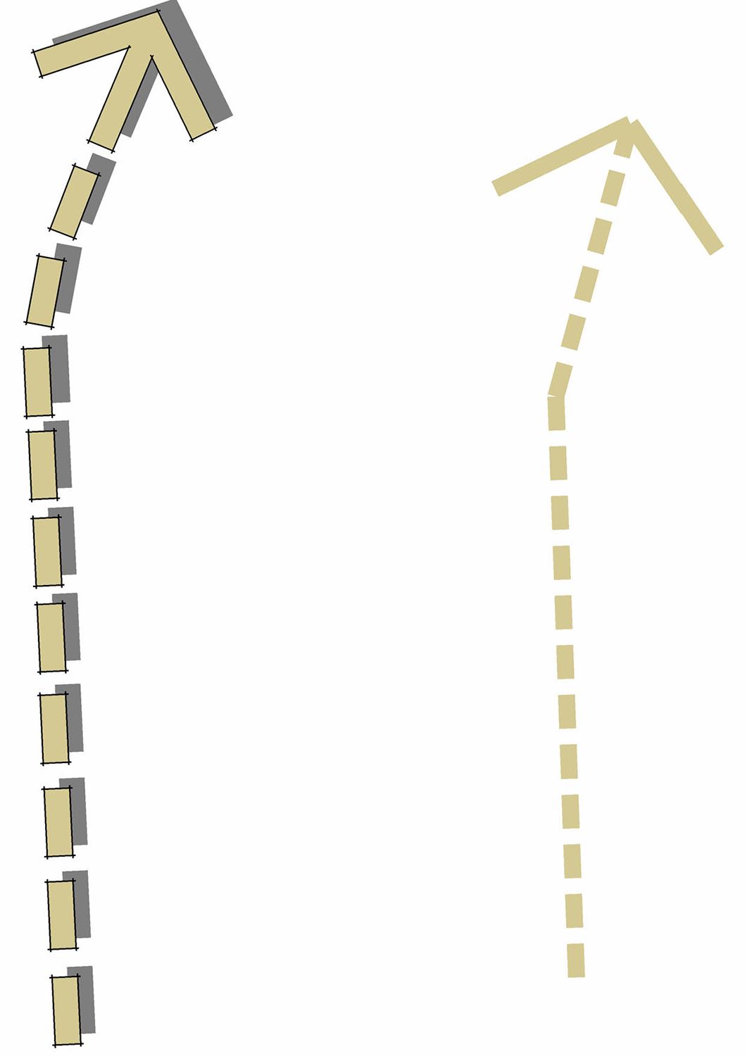
The attached example arrow on the left was created manually and shows what I'd like to achieve after a line style is applied in order to produce urban design annotation with a sketchy hand drawn effect.
The arrow on the right was created with line styles but the faces do not cast shadows and effects such as extended edges and profiles don't appear to work on it. Each one of the dashes appears to be a face when I click on it but they don't cast a shadow.
If it isn't possible at the moment could it be made to behave in the way I've described?
Also could arrowhead styles be added to the settings?
-
Your manually drawn version looks so much better

Because the 2dTools' styled-lines, text etc are intended for 'flat graphics', they have all if their edges hidden and they are also set not to cast/receive shadows.
To change this for an existing entity, switch View > Hidden Geometry ON, then Edit the 'group' and use 'Entity Info' to unhide selected edges, and change the shadow cast/receive settings of selected geometry/groups too as desired...
2d text etc is always made floating a mm or so above its base level, to avoid z-fighting with any surfaces, therefore its shadow casting is unset so it doesn't reveal that... but you choose...You can easily Move objects up in the Z [blue] so they cast shadows on surfaces/ground below them.
If you have Layout [i.e. Pro] then many of these 2dTools are often superfluous to your needs - as flat-2d-graphics are easily made in app ?
-
TIG, thanks for the reply and explanation. It works fine now that I've changed the properties. With a bit of fiddling with the arrow head manually it should look very similar to the fully manually drawn version and will be a big time saver.
I do have Layout but I use Adobe Indesign for graphics but I'll maybe have another look at it as it's been some while since I've tried it.
-
I cant find this plugin on the SketchUcation Plugin Store.
-
If you click the 'Download' button in the first post of the thread it takes you directly to it.
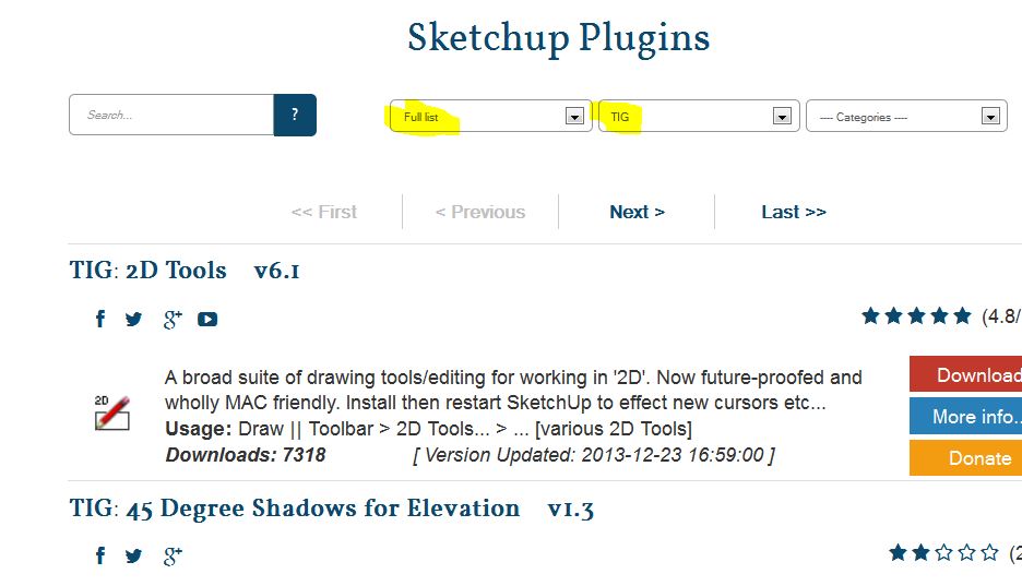
If you search the PluginStore on SketchUcation, select Author TIG and 'Full list'... then it's the first one.
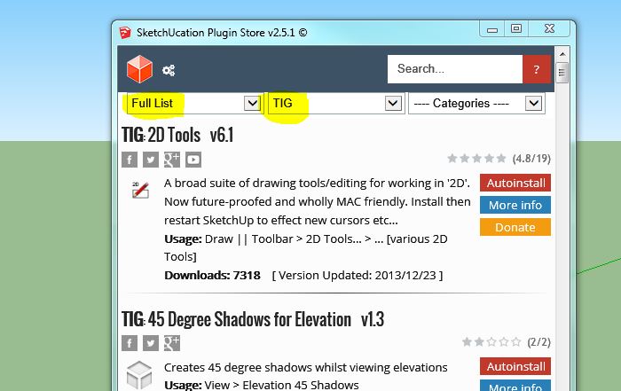
From within Sketchup - PluginStore again search TIG, 'Full list'... and again it's the first one.
-
@tig said:
I think this is down to tiny geometry again.
SketchUp tolerance is ~1/1000"
3mm is approaching that for the tiny facet sizes and their end points being considered equivalent...
When the fillet tool rounds a corner like that there should be no residual lines anyway!
The faceted arc has a first/last section at such a shallow angle to the side that the point is confused.
If you delete the two edges and redraw them, being sure to snap to the ends of the fillet-arc, then they will be 3mm long and dimension correctly.
See the zoomed view attached...It is a plugin that changes the quantity (in selected groups of components, curves) segments in arcs and circles?
I could draw the segments set to 6 (R 1 mm arc are ok) and prior to export to DXF* change all the arcs ang circles for example S30.
Robert
- Free Plugin DXF export does not save arcs and circles as true arcs, only segments.
Robert
-
You can only change the segmentation of arcs/circle that are '2d'.
That is an arc/circle that has no faces or is associated with only one face.
If you have made extrusions you cannot change the segmentation - because that curve now forms part of a 3d object.
You can select a '2d' arc/circle and use 'Entity Info' to change its number of segments.
If you have lots to process there is my Plugin available...
'ArcCurve_set_segments'...
http://sketchucation.com/pluginstore?pln=ArcCurve_set_segments
http://sketchucation.com/forums/viewtopic.php?p=158903#p158903
It runs from a Plugins menu item or the Ruby Console...
It will change the segment count of all preselected arcs/circles IF it can... i.e. they are '2d'... -
@tig said:
If you have lots to do there is my Plugin available...
'ArcCurve_set_segments'...That's what I've been looking for.
Thank you!Robert
-
I am having a problem with setting the Alignment for the 2D Text Tool. The only thing that seems to work is Center. It appears that maybe the ]" at the end of the work Right and the "[ at the beginning of the work Left are causing a problem.
If I try to right align text, it goes through the dialog just fine but does not create anything.
Also, on the Line Style, how do I create my own custom line style?
I am running SU 2014 on Windows 8.1
-
@ntxdave said:
I am having a problem with setting the Alignment for the 2D Text Tool. The only thing that seems to work is Center. It appears that maybe the ]" at the end of the work Right and the "[ at the beginning of the work Left are causing a problem.
If I try to right align text, it goes through the dialog just fine but does not create anything.
Also, on the Line Style, how do I create my own custom line style?
I am running SU 2014 on Windows 8.1
Remember that the 'alignment' of 2d text [which is what 2d text is - just no extrusion and editable...] does NOT place the text-component's insertion point in different places, it's always bottom-left: the alignment affects how multi-line text is formatted - 'left' and the lines of text align to the left 'margin', right the lines of text align to the right 'margin', and 'center' will center the lines of text. You can of course alter the axes [aka insertion-point] of any component by selecting an instance and using the context-menu item to change it.BUT now I do have a suspicion about some Ruby v2014 compatibility error [your report of the ][ brackets] - watch for the update
The custom LineStyle is explained in the 2d Help docs...
Activate the LineStyle tool, right-click in empty space to call up the settings dialog, choose '<Custom Style>' from the end - in the next dialog enter a string - It must consist of<space> .(dot) only. Repeat it with a trailing <space(s)> to suit your needs...
It is named thus'MyStyle~.... .... '
The custom-pattern is saved with the model...However, the LineStyle dialog suffers from the same ][ brackets issue - I fix that too...
Watch for the update shortly...
-
A update [v6.2] is available in the PluginStore.
http://sketchucation.com/pluginstore?pln=2Dtools
it fixes some v2014 glitches with some drop-down lists in dialogs for 2dText & 2dLineStyle. -
@tig said:
@ntxdave said:
I am having a problem with setting the Alignment for the 2D Text Tool. The only thing that seems to work is Center. It appears that maybe the ]" at the end of the work Right and the "[ at the beginning of the work Left are causing a problem.
If I try to right align text, it goes through the dialog just fine but does not create anything.
Also, on the Line Style, how do I create my own custom line style?
I am running SU 2014 on Windows 8.1
Remember that the 'alignment' of 2d text [which is what 2d text is - just no extrusion and editable...] does NOT place the text-component's insertion point in different places, it's always bottom-left: the alignment affects how multi-line text is formatted - 'left' and the lines of text align to the left 'margin', right the lines of text align to the right 'margin', and 'center' will center the lines of text. You can of course alter the axes [aka insertion-point] of any component by selecting an instance and using the context-menu item to change it.Thanks for the reply. Clearly my fault. I some how missed the comment about applying to multi line text.
-
@tig said:
A update [v6.2] is available in the PluginStore.
http://sketchucation.com/pluginstore?pln=2Dtools
it fixes some v2014 glitches with some drop-down lists in dialogs for 2dText & 2dLineStyle.I updated to this version and yes the drop down lists work much smoother.
However, I am still seeing the brackets on the tools and when I select <custom style> for the line style tool, I do not get the window to draw my style.
-
You don't 'draw it', you input it as spaces and dots in a second dialog...
It worked for me...
Something is up with the PluginStore version - it's not updated...I'll updated again please retry it in a moment...
-
@tig said:
You don't 'draw it', you input it as spaces and dots in a second dialog...
It worked for me...
Something is up with the PluginStore version - it's not updated...I'll updated again please retry it in a moment...
Bad wording on my part.....I understand what you are saying about entering it. I just do not get the dialog box. Are dots/periods the only characters I can use in my style?
BTW: On the text tool with multi line text, it shows centered but the text was right aligned. I could not get left to work though.
Probably something about the Ruby 2.0 that may be causing some conflict. I really am using the tool a lot though and liking it. The only other thing I see is that if I apply a line style to a curve, it does not repeat the line pattern but I found a way to work with that

As I said, I like the tool and it is very useful for me. Now I need to figure out how to draw a regular line thicker and add an arrow head. Right now I go to LayOut to accomplish that.


Advertisement