Terrain data conversion to a xyz-file
-
Hello SCF-Members,
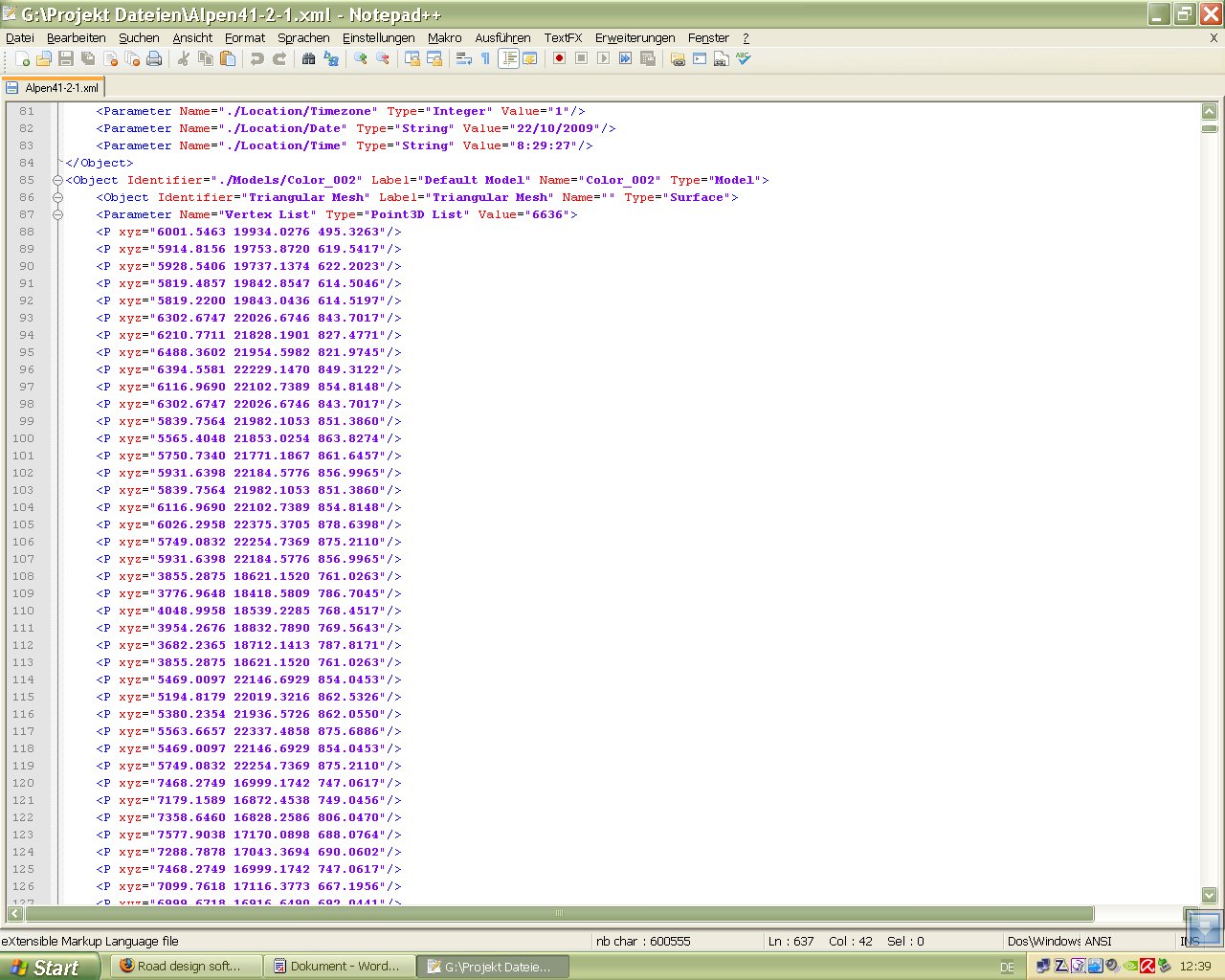
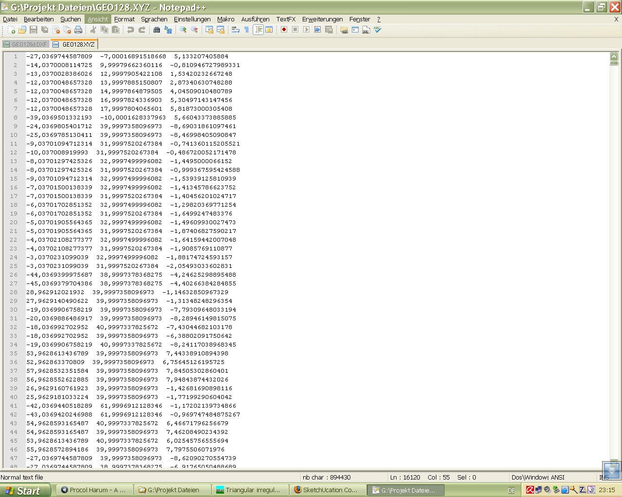
I found a software, Diolkos-Road design. This software is able to read terrain data as xyz-files or dxf. There is also a trial version. In the Kerkythea xml file which was exported from Sketchup i saw there are the terrain data as a list of xyz points existent. A number of CAD programs work with .XYZ files which are comma delimited text files containing just xyz coordinates of points in space.
Does anybody have an idea how to convert this data to a dxf or xyz-file which can be read by CAD. So may be it would be possible to modify a terrain or road with this software.
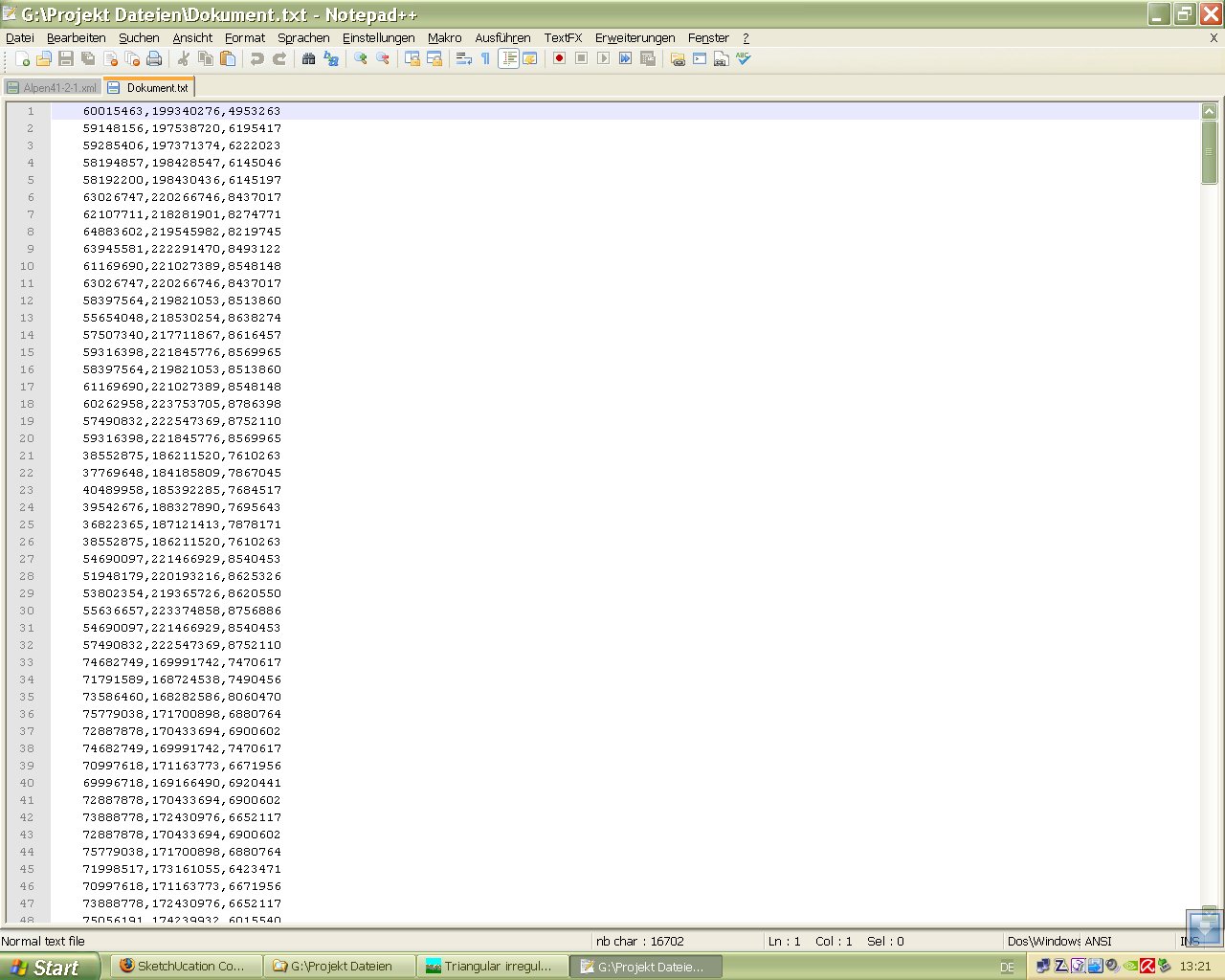
I did a test, i copied the xml data to a text file and renamed it to a xyz file before i inserted commata as spacings.
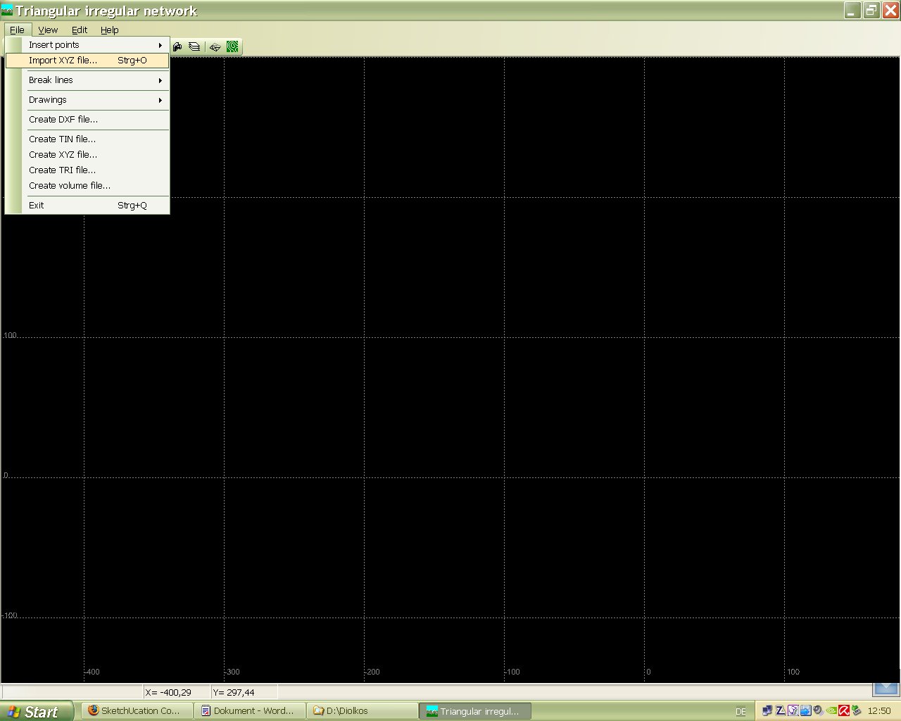
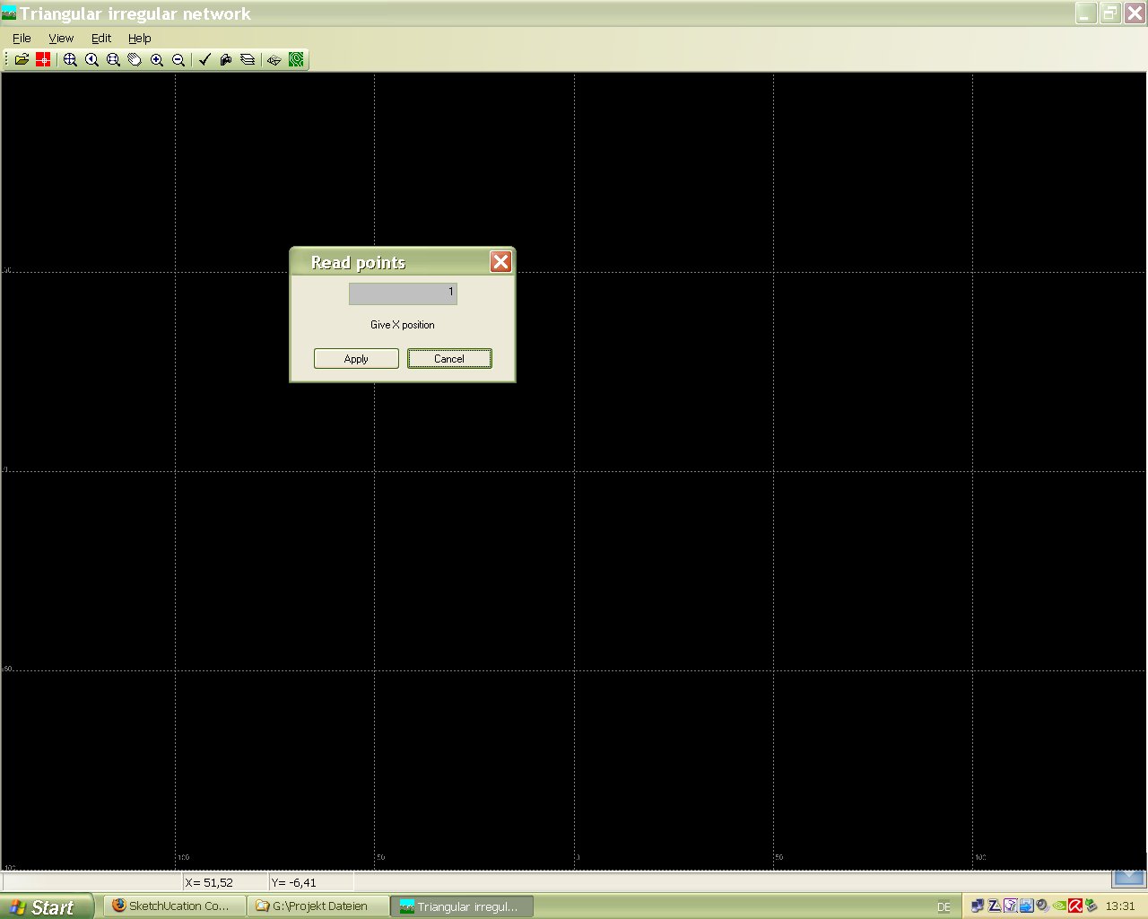
Then i tried to open it with the Diolkos Software. The Read point process asks for three xyz-positions. I'm not shure what has to be inserted. When i apply the predifined values it reports "Erase 575 double points" and nothing happens.
Karlheinz
software link: http://www.diolkos3d.com/diolkos_in_brief_en.htm
-
The website says it can import (more exactly it says "Exportation from/to...") DXF as well. As I see, you have SU Pro,why don't you export your mesh in dxf (after all, that's also a text file)? (Or I don't understand your question).
Also, you can export collada (*.dae) from SU which is again an xml (text) file with the necessary xyz co-ordinates.
-
Hi Gaieus,
I tried to open a from Sketchup exported DXF with this program but i got the message "no points insertion found". I think in the exported dxf there are missing data which the program needs to interpret it as height points. Sorry about my english
KARLHEINZ
-
Ah,I see. From SU you could only export a mesh but not something that CAD uses as height points (which would come into SU as guide points upon import for instance).
And what if you export your skp model to dxf (or dwg),open it in some CAD app and generate the height point data from that (if possible)?
-
for that it would be necessary to have a 3D CAD Software i suppose, but the problem is that i don't have a 3D CAD software.
Karlheinz
-
Well, me neither.

-
Hi TIG,
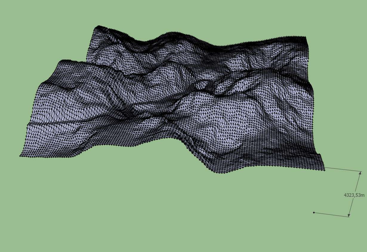
thank you very much. Your AddVertex works fine. Now i will try to get the dxf into this Rod design software mentioned above.
Karlheinz
-
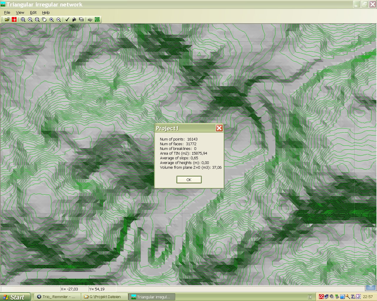
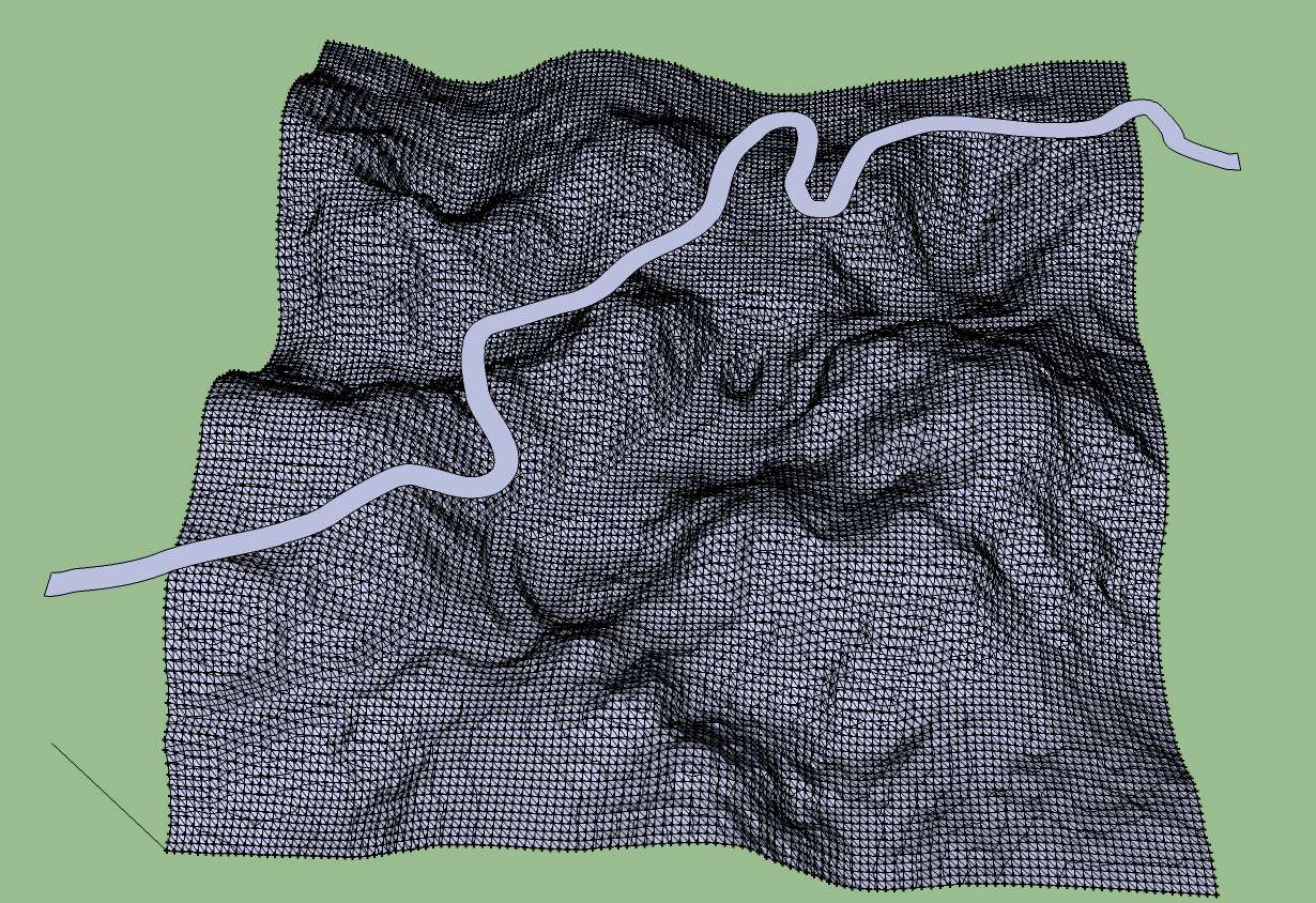
The import of the created dxf worked. Contour lines were created. But the statistic say there are a average of heights (m): 0,00. I exported a xyz file and there are it seems also z-values.
 I'm a little bit confused now.
Karlheinz
-
What units were you working in ? If it's not metres then try changing to mm (Model Info >> Units) before exporting the dxf - it looks like the application receiving the dxf wants it in 'mm'...
DXFs are effectively 'unit-less' - whatever the numbers are in it they are assumed to be the units that are used for the resultant dxf/dwg... so if a 'dimension' is given as 1234 it could be 1234 m or mm or inches or etc...
Try importing the dxf back into SUp and see if it's like it went out - scale it by 1000 and repeat etc ?
It's difficult to fix this without more details...
-
You can export a dxf file containing just 'construction geometry' - see options button on export dialog. To get cpoints at every vertex of a selected mesh use a tool like my AddVertex+ ruby script. It will add a cpoint to every selected edge's vertices. Then export this as a dxf...
In reverse Didier Bur has several tools for importing xyz data into SUp as cpoints and then triangulating them...
-
Hi TIG,
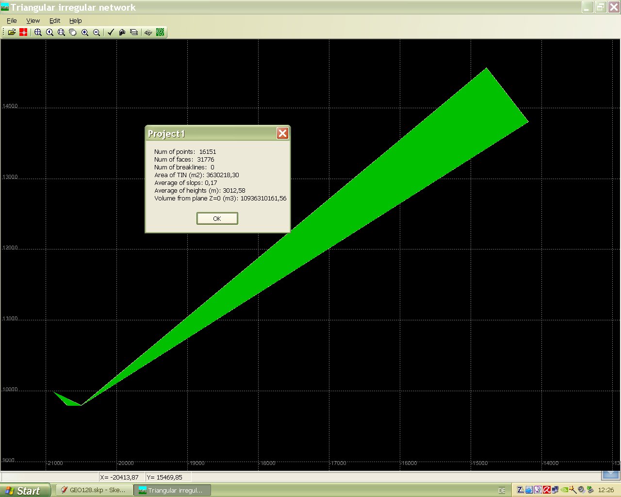
in Sketchup i'm working with meters. The triangulation program works also in meters. I tried your advices but without success. It seems that this program needs a reference point to calculate the height. When i inserted a point in the 3D space in sketchup then a average height of 3012 m is shown but the triangulation is messed up. If you need more information please ask.
Karlheinz
-
Have you added a cpoint at the origin to see if that helps ?
What is the problem exactly ? It's clearly making a surface. Is it making things too small or too big, or wrong in one direction like Z heights ?
Unfortunately I don't know this program you are trying to import in to... -
The idea was to export the terrain into this Diolkos road design software for designing the road contour and afterwards bringing the terrain back into sketchup for further modelling. This software seemed to be simple to work with but it isn't. May be i will find a simple 3d Software where i can do that works.
Karlheinz
-
If it's making a surface that's 'right' but perhaps scaled in some axis wrongly then you can still import it into SUp and scale the resultant component in that axis and relocated the mesh to suit ?
Alternatively model the road in plan 'flat' in SUp, keep it in a group so it doesn't clash with other things, divide it into areas that will have equal slopes, group each bit, rotate the bits about the junction edges, to the required falls and then move them to snap together at common edges to suit, explode them inside the single group, place the group above the surface-copy where you want the road, use the sandbox/stamp selecting the group and the thing will stamp onto the surface with embankments and cuttings [set its 'offset' to say 3m, if the likely cut/fill is 1m], adjust height of whole lot in Z and the cut/fill adjust with that... move the group out of the way and work on the surface-copy...
You now have a3D road with cut/fill on the surface ? -
You can use the basic version (1.2.250) of this software:
Sorry... in spanish. It's for windows, a bit old. You can import any text file, triangulate, and export it to dxf.
-
Thank you Pichuneke,
the program looks interesting. I tried to install it but anything was wrong. Unfortunately i don't speak spanish so i couldn't read the messages given at the installation.
Karlheinz
-
Hi TIG,
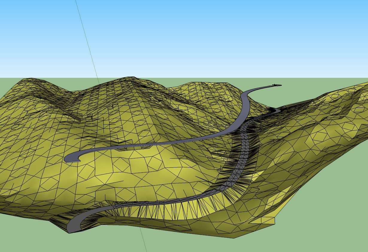
in such a terrain it is nearly impossible to get a good result with that method. I will try it again with the steps i described in the quick road tutorial. It is much more work but the result looks better.
Karlheinz
-
@charly2008 said:
Thank you Pichuneke,
the program looks interesting. I tried to install it but anything was wrong. Unfortunately i don't speak spanish so i couldn't read the messages given at the installation.
Karlheinz
When you start it you must check the box, a message appears that says "Enviaré mis comentarios al foro cuando pueda" (I will send messages to the forum when I can). Don't worry, it's a bit absurd, but the software doesn't connect to internet.
Menu:
Archivo -> Importar -> Ascii (File -> Import -> Ascii). Select the extension of the file (.pun , .xyz , .dat , .txt, .csv...)
A menu appears. You have a box with something like NXYZC (Name, X Coordinates, Y Coordinates, Z Coordinates, Comments). It's self-explanatory.
At left, you have to select the separator: , comma, space, tabulation, columns...
At right:
El separador decimal es una coma: Decimal separator is a comma.
El separador de miles es un punto: Thousands separator is a point (like 2.009).
Click on Importar.
On Menu: Click on MDT -> Triangular...
Maxima diferencia de los lados: Maximum distance between generated triangle, test with bigger values if you have some problems. Click Aceptar.
Fix Manually the problems with the triangulation with: MDT -> Permutar. Click on the green lines, you can see the model changing its shape.
When finished:
Menu: Archivo -> Exportar -> Dxf(3D)
This is a fast guide. Sometimes I add manually points to get better results, the program can interpolate the Z coordinate or a Z value inserted manually.
-
Hi Pichuneke,
thanks for your efforts but i couldn't install the program. Do you have some screen shots from works you have done with this program? to give me an impression.
Karlheinz
Hello! It looks like you're interested in this conversation, but you don't have an account yet.
Getting fed up of having to scroll through the same posts each visit? When you register for an account, you'll always come back to exactly where you were before, and choose to be notified of new replies (either via email, or push notification). You'll also be able to save bookmarks and upvote posts to show your appreciation to other community members.
With your input, this post could be even better 💗
Register Login


Advertisement