[Plugin] Simple Loft alpha 0.1b -- UPDATED May-15-09
-
This looks like a tutorial subject.....
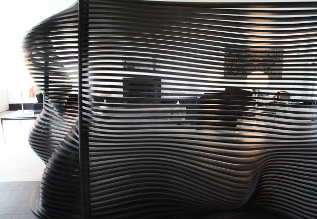
http://www.contemporist.com/2009/05/23/the-phenomena-room-divider-by-sang-hoon-kim/ -
Hi Chris,
Echoing everyone else: Sweet tool!
I have some questions based on the sample video and other examples that folks have posted. The feeling I keep getting is that for any set of curves, there is a range of possible solutions that could be the desired result from those curves and it's not clear how the tool decides what to do.
Certainly, like making a Raku pot, one can just keep trying until something nice results, but this algorithm is not random and it would be nice to have an idea of the parameters to be able to predict what the results might be like in a broad sense.
You seem to be making some assumptions about the angle of the surface as it meets the curves. For instance, in the video, you show two curves first connected by 1 segments, resulting in lines, then connected by 10 segments, resulting in Bezier curves. In that example, it looks as if the tool attempts to have the Bezier curves perpendicular (Blue-parallel) at their ends, but other examples where the curves are a bit more staggered in their alignment, the ends of the Beziers are clearly at an angle.
How is that angle determined? There is clearly something a bit complex going on.
In the example with the pleated curtain top and the simple curve at the bottom, when you introduce the middle curve, the surface goes down from the pleats and meets the middle curve smoothly and then in the lower half the pleats reappear and disappear again by the time the surface reaches the bottom curve.
Personally, I would not have predicted from any of the previous examples that the pleats would reappear in the bottom half. But they do, and clearly that is a result of the angle assumptions that you are making. Might there be settings that would restrict the pleats to only appear in the top half, or is the connection in the lower half between the two non-pleated curves likely to be always pleated because the top half is pleated?
The pleats also seem to ripple in the alternate direction from the top half, again because of some assumptions of smoothness and angles being "transmitted" across the middle curve. If there were two intermediate curves, would the middle section have pleats opposite the top section and the bottom section have pleats pointing the same way as the top? From what I see, I think so.
The result of this transmission of the pleating across the smooth curve makes the result seem more like the folds of a bamboo or reed mat or curtain rather than fabric. Fabric would never have those reverse pleats but a bamboo mat, by it's having more stiffness in one direction than the other, would certainly "transmit" the pleats across the middle curve.
This also gets to the heart of a question that was raised about joining two surfaces as an alternative to using closed curves. On 5/15, watkins posted an image of a bowl or flange shape (Full Bowl) that had circular top and and bottom and about 5 hours later showed the results of trying to use half circles to create the same shape. (Half bowl) As watkins said, "The edges are not suitable for joining."
Would the half-bowl be suitable for joining if straight extensions were added to each end of each half-circle curve and then the last column of facets deleted after generating the loft surface? Always? Only under certain circumstances?
Whether it is always or only sometimes depends on the details of what the algorithm is doing, the assumptions it makes about how it positions the Bezier curves and the angles with which those curves meet the original curves. That is what I'm asking about.
Can you clarify?
I hope this helps,
August -
@august said:
it's not clear how the tool decides what to do
Perfect, its a trade secret!
Just kidding. I'll try to explain the process I wen through to get the curves working how they are. This should clear up a few things.
The curves I use are bezier curves. You'll need to think of each curve as 4 points, much like Adobe's pen tool. A start point, a start handle, an end point and a handle for the endpoint.
With just 2 splines, I take the centerpoint of each collective spline. Then get the vector between those 2 centerpoints. That is the vector I use on each vertex to find the handle point - just follow the vector 1/2 the distance to the other point that the curve will connect to.
Hmm, it all sounds more complex than it is. I probably will have to do a video to show the workings of it.
I can also say that the reason that the version with 1 segment does not have a curve is that, well, it does have a curve. Its still using the curve calculation, but its only finding the first and last point and drawing straight lines between them. So you can't see any of the curve. If you choose 2 segments and then do it again useing 10 segments, you'll see that the middle point that is created on the 2 segment version will match the middle point on the 10 segment curve.
I'm sure that doesn't answer all the questions. But I'm also not entirely sure what all the questions are. Do you just want to understand how the curves are working? THat is what I think you're asking. I'll just have to do a video to explain that I think. I'll see if I can get one done in the next few days.
Chris
-
great tool !!
Thanks chris -
Hey guys, i was posted this on the main forum but no one seems to know or want to answer, or maybe this was asked before. But is it possible to offset a 3d Bezier curve? i.e. one that goes into the z axis?
-
@pr0 said:
Hey guys, i was posted this on the main forum but no one seems to know or want to answer, or maybe this was asked before. But is it possible to offset a 3d Bezier curve? i.e. one that goes into the z axis?
It's best to create a separate thread on this. (Sorry, don't have an answer for your question.)
-
His original post is here:
I've responded (well, just asking for clarification).
Thanks everyone else for the comments.
Chris
-
@chris fullmer said:
With just 2 splines, I take the centerpoint of each collective spline. Then get the vector between those 2 centerpoints. That is the vector I use on each vertex to find the handle point - just follow the vector 1/2 the distance to the other point that the curve will connect to.
Hmm. First, terminology: The splines are the starting curves and the Beziers are the curves that connect the vertexes of those starting curves. Right?
(An aside, what is a "loft"? Is that a standard term? Where does it come from? Is is meant to convey an image of a sail filled with wind or a bedsheet settling down after you've fluffed it in the air? If so, then fabric metaphors rule and the bamboo-mat, reversed pleats glitch.)
So, you find the centerpoint of each collective spline. One point for the top spline and one point for the bottom spline. I'm assuming not the center vertex but the geometrical center of the extents of the spline, right?
A vector between them. A line from the geometrical center of one spline to the geometrical center of the other, then half that distance to create top and bottom vectors. Then those half-vectors are applied to each point on each of the splines and a Bezier generated between them, with those half-vectors determining the angle at which the Bezier curves connect to that splines, top an bottom.
OK, that was one question, the attachment angles.
That explains why the half circles don't generate edges that will join with other half circles. The centerpoint of each half-circle spline is not the center of the arc, it it offset, so the Beziers at the ends of each spline start at each end with an inward tilt, even if all four endpoints of the splines are coplanar. Knowing that should also give the solution to the half-circle joining problem. Extend the ends of arcs with lines until the center of the arc-plus-lines spline lands at the center of the arc.
@unknownuser said:
I probably will have to do a video to show the workings of it.
Not needed for me. But, like with the "bug" about not being able to join half-circle lofts, knowing what it is doing internally can help solve problems.
@chris fullmer said:
I'm sure that doesn't answer all the questions. ... Do you just want to understand how the curves are working?
I'm looking for explanations of the behaviors that don't match my expectations. The half circles not generating edges that could join is one. I think I've got that one, including a work-around.
The other is the three-spline example with all the pleats in the top spline. The pleats "transmit" from the top half to the bottom half while being exactly gone when the surface passes through the middle spline. That is really counter intuitive to me, from the perspective of what you appear to be trying to do. So it falls in the category of a "bug" to me. Not one that stops the tool from performing, but one that generates slightly undesirable results.
The fact that the pleats are gone at the middle spline and reappear, reversed, in the bottom half is indeed explained. You are generating Beziers that run from the top through the middle to the bottom, and each Bezier has four vectors, top, two in the middle, and bottom, that all have identical angles. The path of each Bezier as it passes through the middle is affected by the offset of the pleats and thus transmits that pleating to the bottom half.
All explained, it is indeed doing what you told it to do. No bugs there. But is that the result you actually desired, or did you stop there because the results were pretty?
What I'm getting at is that I think the reversed pleats are somehow wrong. One alternative would be to have no pleats in the bottom half, with the center spline essentially forcing an end to the pleats, but I think that's not right either.
Personally, in the pleats example, I would rather have the center spline modify the path but not force the surface to go exactly through it because that forces the pleats to disappear and reappear reversed, which just looks wrong to me. And I assume it is not an effect that people will be actually trying for very often. The tool generates pretty results and I think people would not encounter that "bug" very often and would ignore it when they do, but it still strikes me as somehow wrong.
I think where I'm leading to is to have the top and bottom be absolutes and have middle splines be guides, not necessarily exact matches. If the middle spline modified the path of what you would get without it, but without forcing an absolute match at that place, I think the feel of using the tool would be more "organic" and the results more like what I think people would expect. I think my desired result in that example would be to have the pleats continue through the middle spline without going to zero and without reversing, but with that spline having an influence on the flow of the pleats.
Maybe I'm looking for the vertexes of the middle spline to act more like Bezier control points rather than absolute vertexes.
Maybe you find the Bezier curve center (inflection point?) between the top and the bottom and then deflect that toward the corresponding point in the middle control spline. Where there is only one control spline, you deflect it half way between? When there are two control curves, you deflect each Bezier inflection point by 1/3 from the control spline point towards the no-controls Bezier point? Or maybe a slider could adjust the influence of the intermediate control splines from zero to absolute. At zero, it would be as if there were no intermediate curves and at 100 you would get the current effect, including the forced alignment to the curve and the pleat flipping.
Personally, since I asked the question that you were suggesting you answer with a video, I'd rather you spend the time trying my slider idea than making a video. But it's your project.
I hope this helps,
August -
hi Chris,
it's blitzing the mac, was ok for three or four hours, giving some extremely curious versions of what I'm trying to achieve.
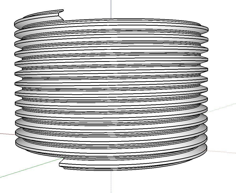
basically it's an accurate thread-form (basic ring), something I've never found a SU solution for
on one attempt it did a lovely job set on 2, but the decided to try 6 instead of the 4 bezier splines to add extra detail and improve the stack ability and end finishing.....
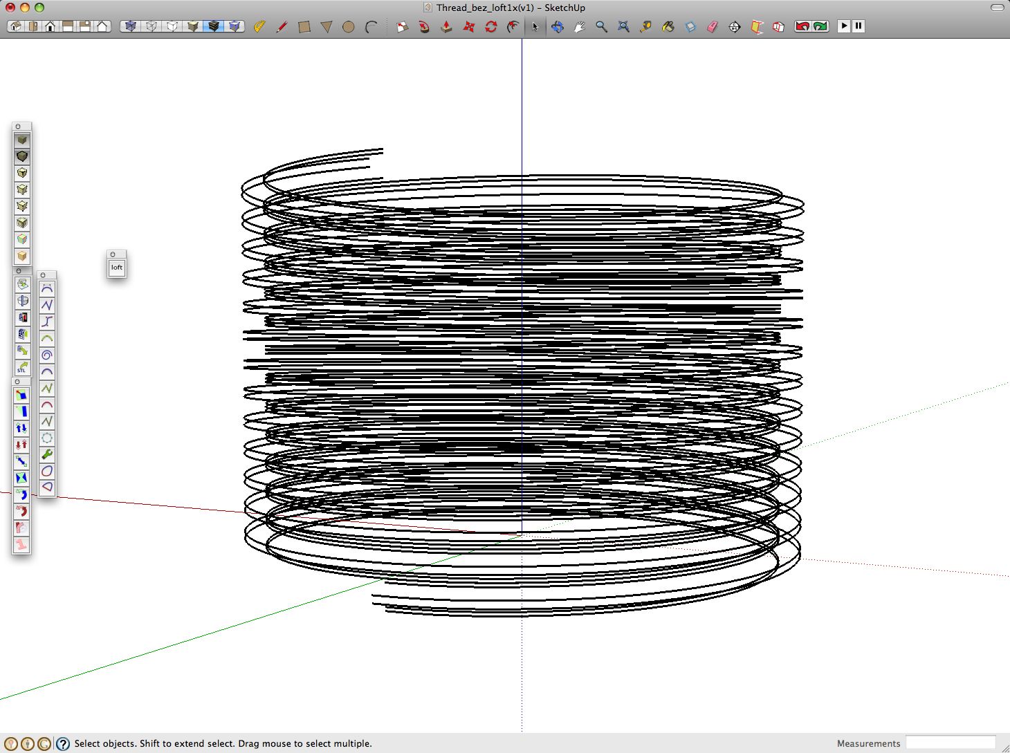
so I deleted that one, built a new spline jig and loft started crashing out SU, I checked everything else, and it's fine now loft is removed so I used skin in 6 separate goes to show what I'm trying to do and attach the skp with the spline set, the spline jig, and the skinned version if any one want's to see if it works on there set-up (a mac maybe...)
the over lap gap is very close, so it's best to select splines well clear of them...
UPDATE.. I found I had save the Setting 2 loft in another drawing, but it locks out any new or old drawing I try to open it in, so a screen shot has it buried in a tube...
the reason I'm trying to do this is the follow me tool twists the thread shape even on a single quadrant.
machine threads, springs and candi-stripes are are good test if of accuracy of lathe type tools..
I do like your stuff, keep up the good work.... please
john

-
Hi, I'm not sure which of these is the real problem, but I think that its not set up to work with groups/components. So explode the splines first. Then probably also erase the construction points and construction lines. That solved it all for me. It splatted otherwise.
Chris
-
@driven said:
the reason I'm trying to do this is the follow me tool twists the thread shape even on a single quadrant.
Hi John,
The problem you are trying to solve has been addressed with other plugins. Chris' Loft plugin is about generating fluffy, billowy, organic, drapey shapes and is probably not the right tool for your job. Your task is out at outer reaches of what you might be able to force the Loft plugin to do.
I wish I could point you to the non-twisting Follow-Me plugins, but I've only seen discussions of them, I have not tried them myself yet, so it would take some research to give you a suggestion.
I'm pretty sure that someone else following this thread knows what to tell you.
I hope this helps,
August -
I know I have not explained the inner workings of the script very well yet, but its partly because the next version changes some things, or exposes a a little more of how it works. So its not quite worth going into detail yet when its about to change (a little).
But....the loft might exactly the right tool for something like what he wants. Especially the next version. It has the ability to control the strength of the curvy-ness that is being given to each bezier connection. So instead of really trying to be curvy, you can minimize that a little and make it mostly flat, but rounding just the areas closest to the splines.
This is why the script is designed to actually run through every given spline, and not use the splines as "handles". It gives more accuracy this way because you CAN control where it runs - directly through each spline. And with the next addition of being able to control the strength of the beziers, its pretty handy.
All that being said, I don't prefer to use lofting tools that much. I'd probably just use my bend script or one of the follow me and keeps. They are all good alternatives, especially while this script is still so difficult to use.
Chris
(I've been debugging my next version of the script most of today with limited success
 )
) -
cheers Chris and thanks for the comments August,
it works, exploded the curves and it's a one click job, fantastic
@august said:
I wish I could point you to the non-twisting Follow-Me plugins
I've been searching, but the advantages of this is I have a lot of control over the bezier profile and path (thanks to Fredo) and a simple rig made with xformclone.rb, so skinning between only distorts the additional sections I add at both ends, which trim square with an intersect with a plane, then it's just 'movecopy' X times...
A good tool is a good tool regardless of it's original perceived use...
thanks again chris
john
ADDED: it did this in one go, not just for drapes.... took 10 mins but no crash, this time.
Added More: Spoke to soon, this is in the components window, it seems to have locked while writing the thumbs, having completed the drawing, I'm in and out at moment so will give it time and see if it recovers, out of curiosity..
-
@driven, there is a very good plugin to screw profile or shape named "screw1_5.rb or screw_21.rb I prefer the first one".
However @ Chris I can say I enjoy your plugins as much I enjoy Fredo's, but this doesn't want to run on my mac.

@unknownuser said:
undefined method
select_tool' for nil:NilClassError Loading File clf_simple_loft_loader.rb undefined methodselect_tool' for nil:NilClass -
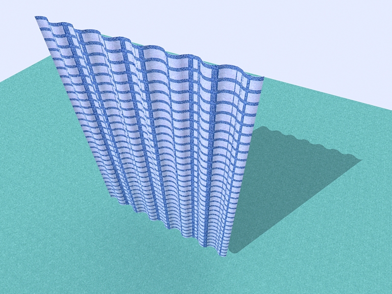
fun little tool. Thanks again Chris.
-
Just to let you know, this plugin creates an empty group in every model, it may seem small, but SketchyPhysics (By Chris Phillips) Simply refuses to work with it.
-
Oh really? Oops. I'll try to make sure to get that fixed on the next round. I must be forgetting to delete a group somewhere in the mix. Thanks for pointing it out!
Chris
-
wow that's exactly what I need

-
Chris, I've been playing with your Loft plugin and Driven's screw thread file. When I first opened his file I was able to create his threads by selecting two curves at a time and using 1 for the number of segments. I tried it by selecting all six curves and got a Bug Splat. I reopened the file and cut the curves down to a quarter turn thinking I'd give it fewer faces to create. Here's the results. In the background you can see a test loft with two 12-segment arcs and five loft segments.
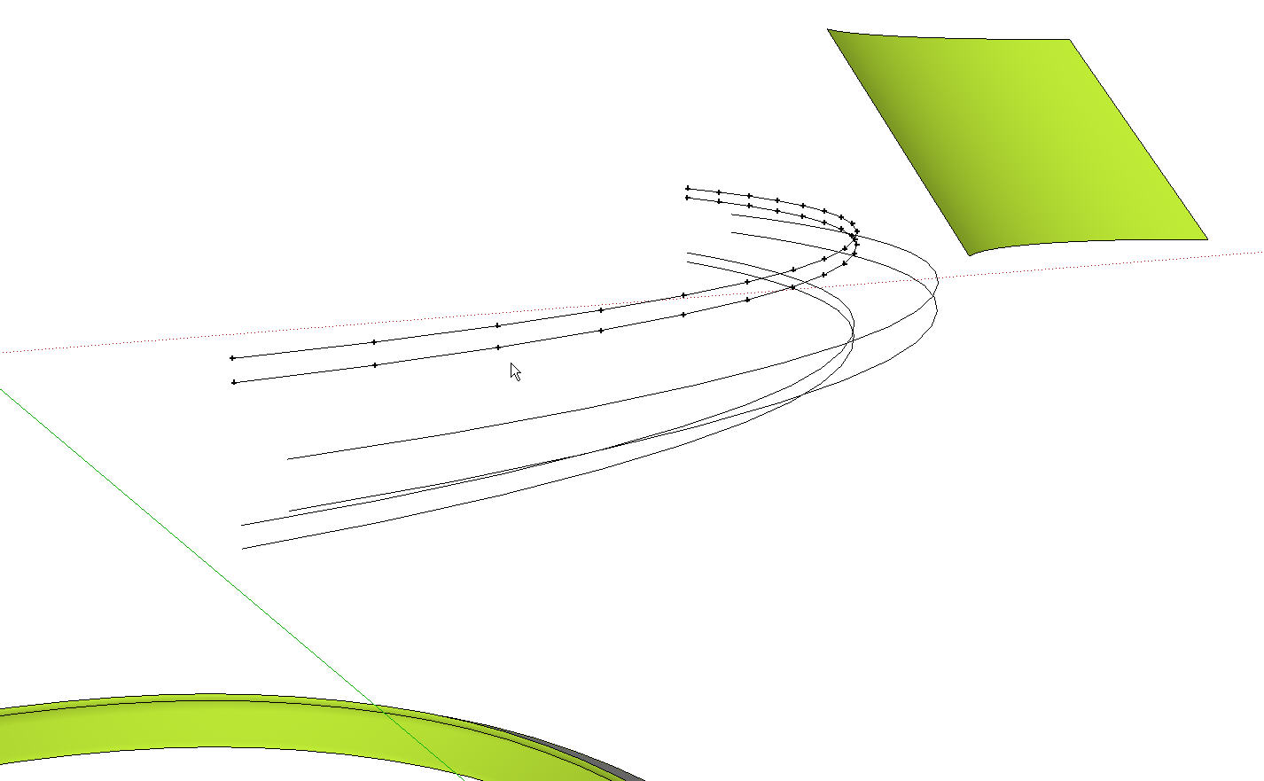
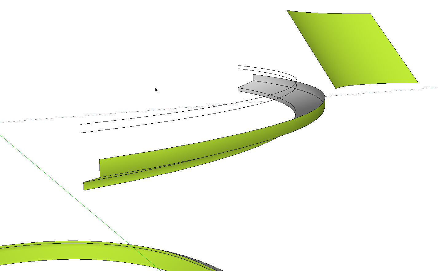
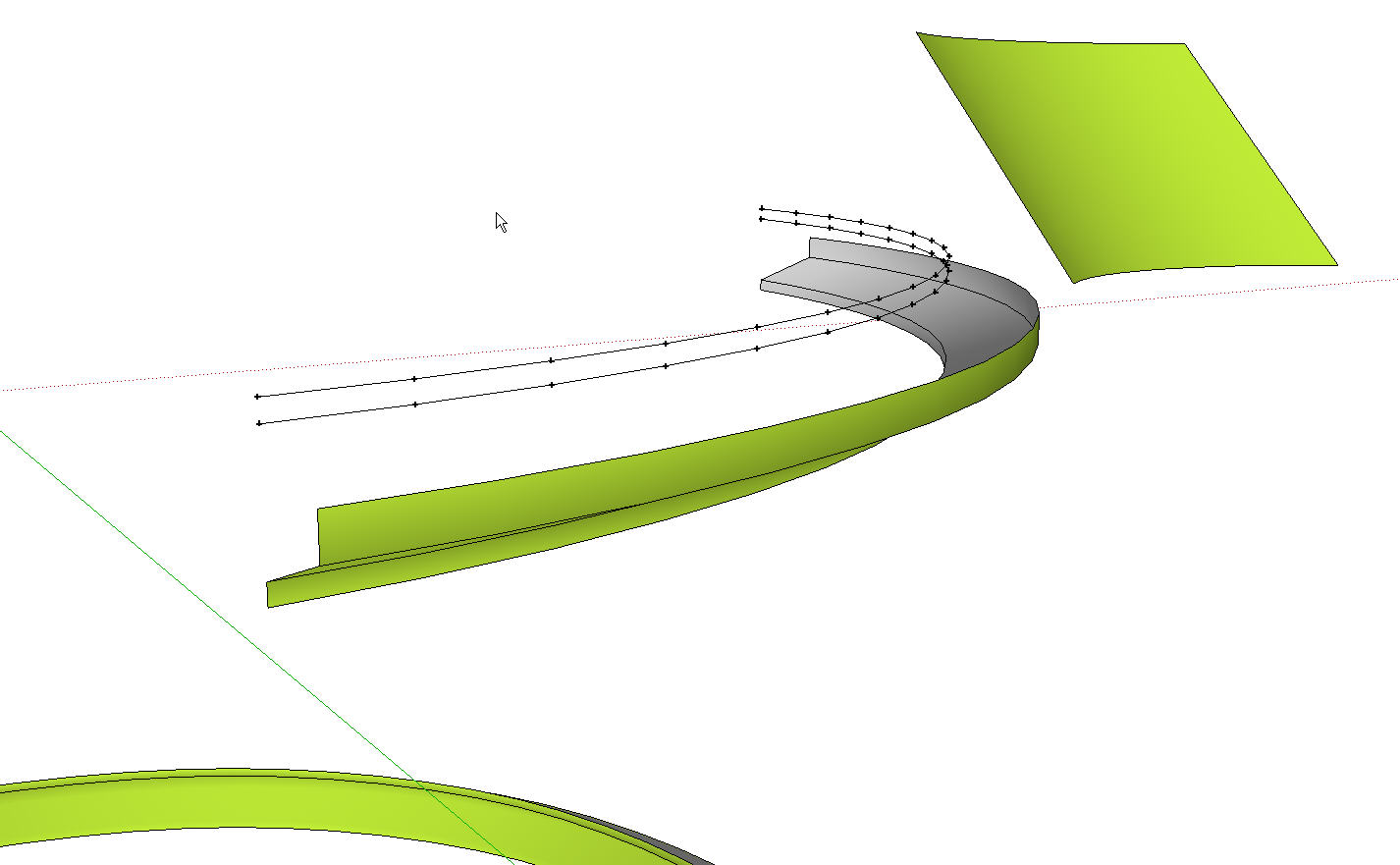
The guidepoints are interesting but not quite what I expected.
-
That means it is crashing for some reason. Normally to do with the selection including a non-edge item, or also if the segment counts don't match. I'm not sure which. You can upload the model immediately before that point and show me which lines to click on and I'll figure out what it is.
Hopefully the next version wll clean some of that up.
Chris
Advertisement


