Importing DXF
-
I outputted a line drawing of a shape in DXF from another CAD system. I then Imported it into SU. The shape came through perfectly, and I went through it and made sure it was completely closed at all the intersections. I can now erase and manipulate all the line segments, and can even rotate it. But it will not form a surface, so that I can use the push-pull tool on it. I even drew over one of the line segments, like the Dummies book suggested, but that didn't work, either. No surface.
What should I do?
TheDuke
-
Try turning on color by axis. See here:
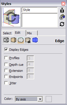
This might show you the lines that are giving you problems. You may very well have non co-planer edges. This is the first thing I check when I cannot get a face to close.
Hope this helps.
-
I did that, and two small segments showed red and green. All the rest were black. It is an irregular shape with about 150 segments, and those were the only two that were aligned with any of the axes. I assume that DXF doesn't have any depth info in it, so I thought the resulting shape would be flat. It came in flat on the ground plane, and it looks absolutely flat when I rotate it.
Any ideas?
TheDuke
-
I don't quite get whether the shape id 2D or 3D. If it's 2D it's almost certain that at least one of the vertices is not coplanar with the others...if only by a minute amount.
There is a Ruby called Flatten which will solve that problem for you. http://www.smustard.com/scripts/Failing that, you could try exporting it as a 2D CAD file and then bringing it back in again. That ought to have reset all Z values to 0.
-
@theduke said:
I assume that DXF doesn't have any depth info in it, so I thought the resulting shape would be flat.
There is no difference in the contents of a DWG or a DXF file, DXF is only an ASCII version of a binary DWG. So whether there are Z values in your export depends wholly how the DXF exporter of your CAD program is written and configured.
Other reason why the shape won't fill could be that the segments, or one of them, are very small-the SU limit is somewhere near 1 mm. I also think that there may be a limit where the number of segments becomes too large for SU to handle.
One technique I use in cases like this is to draw diagonals across the shape to see if they fill, and if successful then try to erase them. This can also help to isolate the problem parts of the shape.
You could also try to fill the shape with the Sandbox from Contours tool, and erase the resulting zillion diagonals afterwards.
Anssi
-
And if you are still having trouble post the model here, I am sure one or more of us would be happy to look at it.
-
Hi TheDuke, hi folks.
You may easily test if any endpoint is not on the intended plane by using the Text Tool.
This tool has the interesting property of proposing default text that often serve useful purpose. On an endpoint it will gives you the X,Y and Z coordinates of the point. Boost the unit precision to the max (0.000001) and you can see if any point(s) is (are) not on the same level as the others.
The tool propose the following default text for these objects:
-
Endpoints : X,Y,Z coordinates
-
Lines : line length
-
Faces : area
-
Groups :"group name" if the group is named, otherwise "group"
-
Components : "component name" if the component is named, otherwise "text"
Just ideas.
-
-
The principal use of this shape was to create a proper sized human mannikin, for use as a "fit test" tool in the design of an RV trailer I am working on. Since the main goal is the design of the trailer, it's no longer practical to continue to wrestle with this part of the problem. I simply cut out a squared off "robot" shape with the standard SU tools, and will make do with that, for the moment. I really appreciate the excellent responses, and may come back and pursue this subject further. But, for now, thanks to all of you for your willing help.
TheDuke
-
The problems you are experiencing are most likely due to
- Linework is not coplanar (some linework either sloping in the z axis or at totally different elevations) and / or
- You have dirty CAD linework - Overshoots, Undershoots, Lines not Intersecting correctly, Slivers, Double linework and other such Junk / Spaghetti.
Try flattening all linework in your CAD program - if you have access to Autocad - the Command is FLATTEN if you have Express Tools loaded - then you'll KNOW its in 2D.
...
Clean up the CAD Linework as much as possible if it's at all feasible.Alternatives - Visit Smustard:
http://www.smustard.com/scripts/Download 2 scripts - Flatten and Make Faces.
Once Data Flattened - Run Make Faces Script.
...
Hope this helps.
Howard L'
Hello! It looks like you're interested in this conversation, but you don't have an account yet.
Getting fed up of having to scroll through the same posts each visit? When you register for an account, you'll always come back to exactly where you were before, and choose to be notified of new replies (either via email, or push notification). You'll also be able to save bookmarks and upvote posts to show your appreciation to other community members.
With your input, this post could be even better 💗
Register Login


Advertisement