Medeek Engineering
-
Version 0.8.2 - 09.09.2025
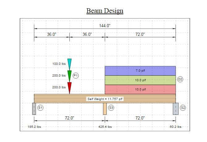
- Enabled loads and reactions (values) within the load diagram.
- Fixed a bug with end supports that are not centered on the start or end of the beam.
- Improved the formatting logic (SVG and HTML) for the load diagram.
-
Working on assembling the actual engineering part of the report now, adjustment factors, shear, moments, deflection and bearing checks.
-
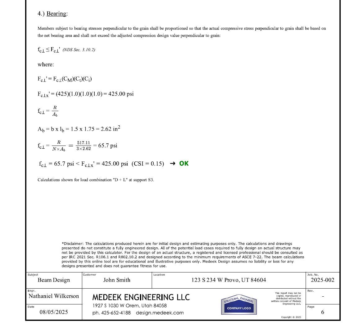
First look at the bearing check:
I also need to update my disclaimer, the disclaimer shown is for my previous online calculator, it needs some changes.
-
yeah i think keeping the disclaimer a bit more succinct - the first sentence, skip the next two, and keep the rest plus you might include the user assumes all liability for the use of this report blah blah blah.
-
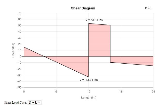
Spent the last two days adding in some additional code so that the vertical jumps in the shear graph (at point loads and supports) are actually vertical. It was a bit more complicated than I originally bargained on but I think I finally have it figured out:
The code seems fairly robust but tomorrow I will throw the kitchen sink at it to see if I can find any weaknesses in the algorithm.
I have't been posting much lately but that is because I've had my head buried in the code. Most of this engineering code is completely new (not my typical plugin stuff) so there is no refactoring old code or any other shortcuts I can take. Some of the old beam calculator is relevant however since it was so limited in its application I'm kind of on my own with this new calculator.
-
The vertical jumps now look at lot better. So far it seems pretty solid:
-
Here are the different EB (Euler-Bernoulli) and TIMO (Timoshenko) deflections for the same simple supported beam with a basic UDL (no self weight, just the external load applied) :
My parameters are:
2×10, L=144 in, E=1.7e6 psi, I=98.931 in⁴, A=13.875 in², G=106250 psi, κ=5/6
As you can see the Timoshenko analysis yields slightly more deflection since we are accounting for deflection from both shear and bending. According to my calculations my results are within less than 0.05% of the theoretical value so I think the algorithm is working correctly
Now I need to check a few different multi-span configurations as well as overhangs to make sure everything is indeed robust.
When I calculate the Timoshenko beam I'm wondering if I should adjust the tabulated E value since it is being adjusted for the shear already by %3 for sawn lumber per Appendix F of the NDS (Sec. F.3). So the listed value is is actually 3% larger than the (shear-free) or true value of E.
-
would an easy way to compare E with and without the adjustment in case it's significant enough for someone to review their parameters? e.g. https://woodengineering.com/2022/07/16/shear-free-eeee/
Glenn
-
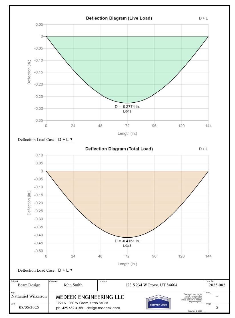
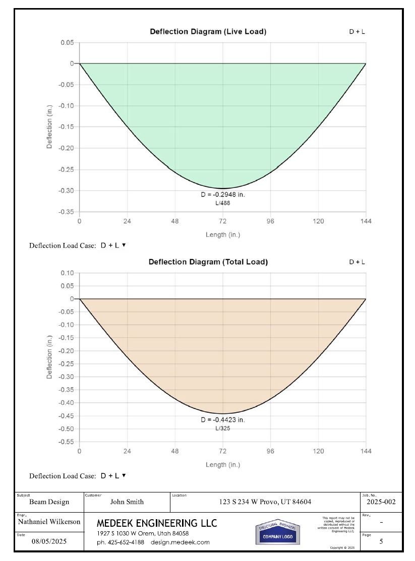
I still have completely finished the PDF reports since I've had my head so buried in the Timoshenko stuff for a couple of weeks (probably not a good use of my time but I couldn't resist). Here is some output for a couple of cases (two span and three span beam, equal spans with a UDL). What is interesting is the shape of the deflection graphs for the Timoshenko analysis. I think the numbers are correct but to be honest I really don't have another 3rd party program I can fully test against.
I'm using a kappa of 5/6 and a G of 1/16 the E value, so in this case G = 106,250
Also I am just using the listed value of E for my Timoshenko calculations even though it already includes a 3% bump for shear built in.
EB = Euler Bernoulli, TIMO = Timoshenko
As a sanity check I multiplied my calculated value of G above by 10,000 in the code and then ran the TIMO analysis, the results are almost identical to the EB analysis as expected, so that tells me that with an extreme stiffness the TIMO degrades to an EB analysis as it should in theory. Here are the links to the TIMO analsys with a 10,000X inflated G:
-
Here are a couple examples, everything should be complete, but I will now spend the next couple of weeks error checking and seeing if I can break the engine or the report formatting. I will also need to test against other third party programs to make sure all my calcs are indeed correct. It is amazing how easy it is to make errors in the code on something this extensive.
https://design.medeek.com/resources/engplugin/TEST1/EB_TEST1_2SPAN_1POINT_REV8.pdf
https://design.medeek.com/resources/engplugin/TEST1/EB_TEST1_3SPAN_3POINT_REV1.pdf
Currently the calculator will only handle sawn lumber beams. Once I'm fairly certain I've eliminated any bugs or other issues I will then extend the logic so we can handle glulam and timber beams. Once that is done I will probably next work on LVL, LSL, and PSL and then finally I will include the ability to analyze various I-joists from the major manufacturers.
I've been slowly working on this for about three months now, probably another month to go.
-
Version 0.8.3 - 11.12.2025
- Enabled a detailed and simple engineering report/analysis for sawn lumber beams.
- Added an option to switch between Euler-Bernoulli and Timoshenko beam analysis.
- Report now includes live load and total load deflection graphs.
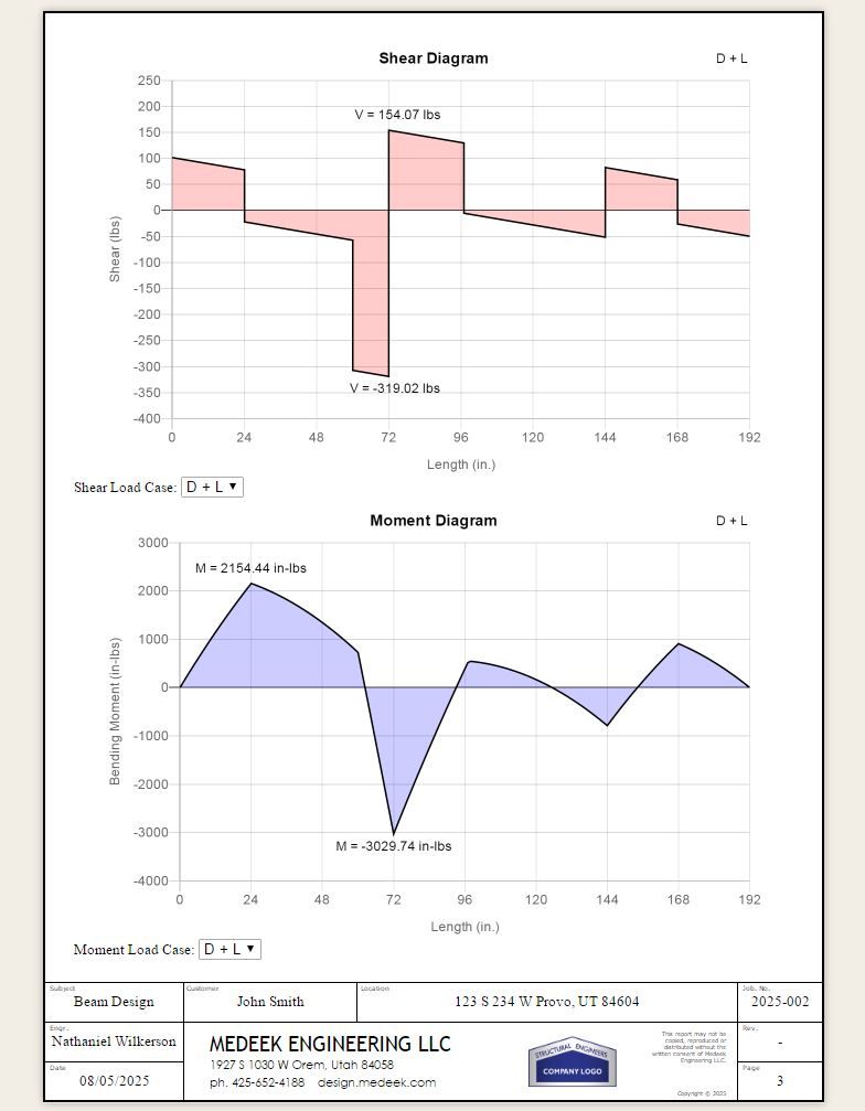
- Shear, Moment and Deflection graphs can be toggled to all load combinations within the report.
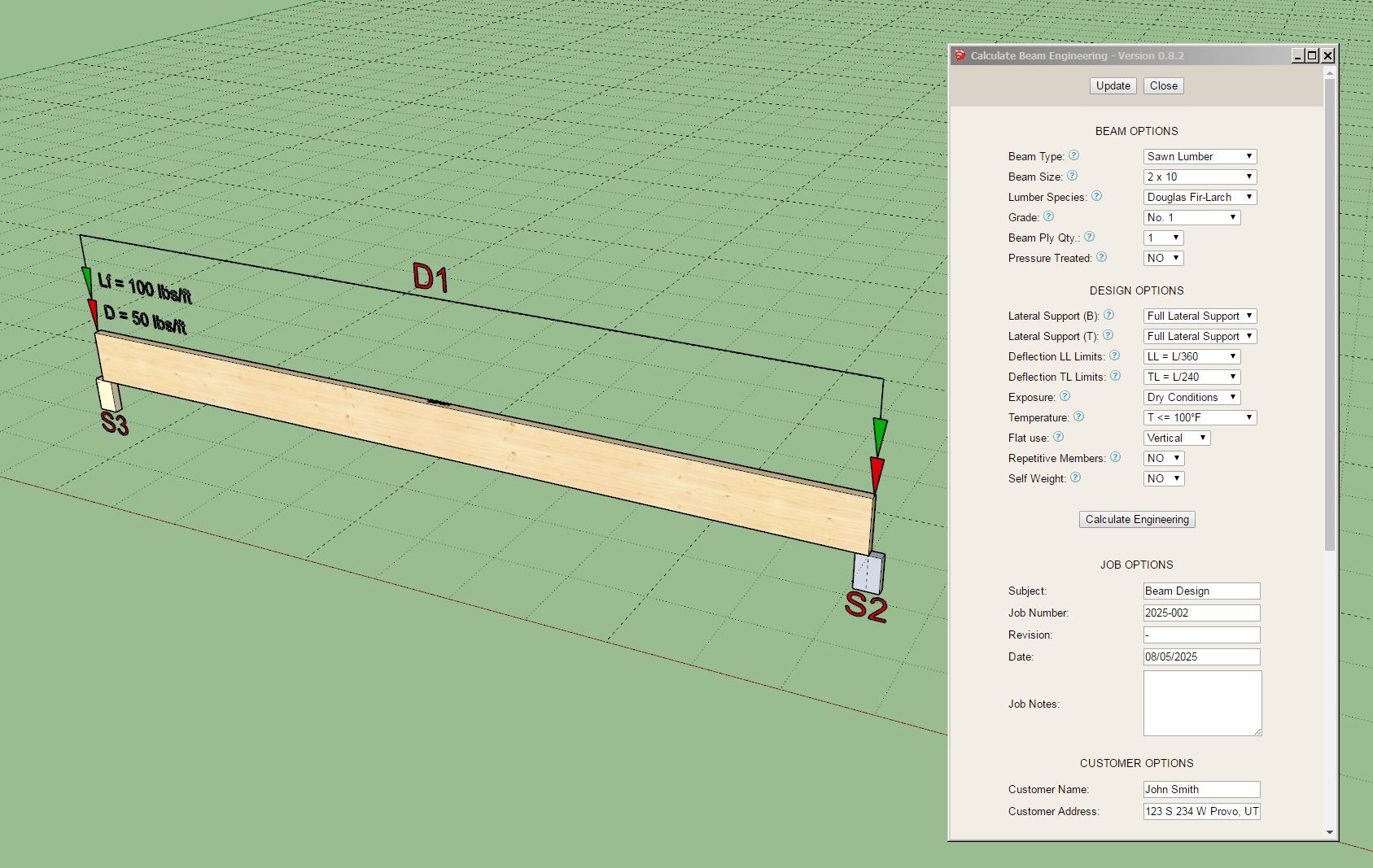
Tutorial 1 - Beam Calculator
I'm very excited about this release, it is the first time in history (that I know of) that one can do actual engineering all within SketchUp. The API is magical, you can turn SketchUp into just about any thing you can imagine.
-
Version 0.8.4 - 11.21.2025
- Fixed a bug with partial bearing at end supports.
- Added the bearing area factor (Cb) to the bearing calculations and adjustment factors table.
- Added the "Braced at Supports" option to the top and bottom lateral bracing options.
- Fixed the lateral bracing algorithm for bending so that blocking at supports is enabled (bracing at top and bottom).
- Fixed the algorithm for lateral bracing so that the unbraced length is correctly calculated.
-
Tutorial 2 - Lateral Stability (18:31 min.)
-
The other issue I am a bit unclear on is the unbraced length (lu) especially in the case of checking negative moments in multi-span situations (unbraced bottom). I've checked a number of examples in Donald Breyer's book "Design of Wood Structures". Rather than considering the lu as the actual span he is calculating the lu as the distance between the points of zero moment. I could use a bit of clarification on this. Section 3.3.3.4 of the NDS (page 17) only talks about the distance between points of intermediate lateral support.
After giving this some more thought and digging through the NDS a bit more I think the reason that Breyer makes this assumption is that the language in the NDS for computing the Cv (volume factor) does say the distance between points of zero moments. He then seems to extends this idea to computing the CL by using the same logic to determine the unbraced length (on both sides of a support). See example 6.28 in chapter 6.16.
My only problem with this is that it would seem like it would be unconservative in many cases with multi-span beams where you are computing the CL for negative moments (at supports). However by using the full intermediate span length as the unbraced length perhaps it is too conservative. I wish the NDS would give more guidance on this matter, I can only guess at the intent and supposed correct algorithm at this point.
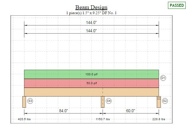
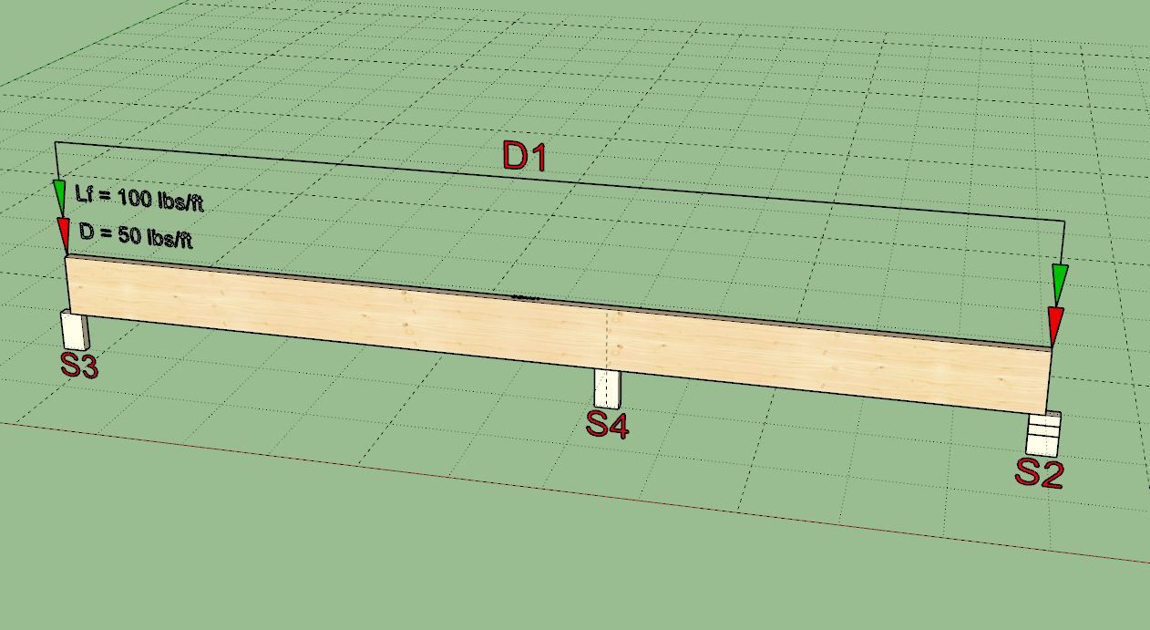
Let's consider the example shown in the image below:
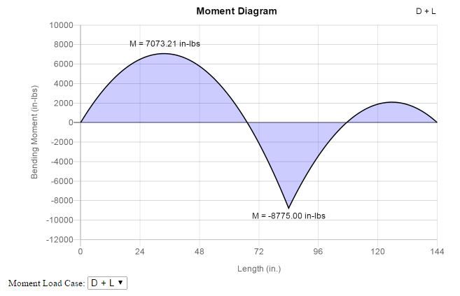
If we consider that there is no lateral bracing at the intermediate support at 84" (bottom of beam) then per Breyer's method the unbraced length is between points of zero moment (x=67" to x=108"), so the unbraced length for the negative bending (neg. moment) is equal to 41". However I would argue that it is the full beam length, both spans, so 144".
If we do consider that the beam is laterally braced (bottom of the beam) at the intermediate support at x = 84" then Breyer considers the worse case of the two conditions 84 - 67 = 17" and 108 - 84 = 24" and he concludes that the unbraced length should be 24". I would look at both spans on each side of the support or max. negative moment and take the larger of the two 84" > 60", so the unbraced length should be 84".
Thoughts? Am I too conservative?
On a slightly different note I would use 41" length to compute my Cv for the negative bending (for both cases given above). This is per the NDS verbage (Sec. 5.3.6).
-
Version 0.8.5 - 12.05.2025
- Updated the licensing system with an improved algorithm (bug fix for SU 2022 and greater).
- Added a "Deflection Analysis" tool to the main toolbar.
- Added deflection analysis as an option within the beam context menu.
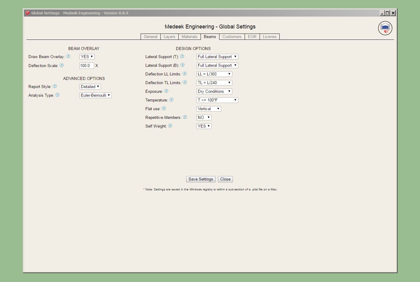
- Updated the "Beams" tab of the Global Settings with various options.
Nathaniel P. Wilkerson PE
Medeek Engineering Inc
design.medeek.com -
just in case you needed another rabbit hole... https://www.apawood.org/ftao
-
After the Beam calculator I need to put together the post/column calculator, then the footing calculator, then the shear wall calculator and then maybe the FTAO shearwall calculator.

Hello! It looks like you're interested in this conversation, but you don't have an account yet.
Getting fed up of having to scroll through the same posts each visit? When you register for an account, you'll always come back to exactly where you were before, and choose to be notified of new replies (either via email, or push notification). You'll also be able to save bookmarks and upvote posts to show your appreciation to other community members.
With your input, this post could be even better 💗
Register Login


Advertisement