Tax_Engineering v10.1 [plugin update]
-
"Roller chain along" done!
Also added "Selection report" and "SU links".
Enjoy.obs: If you use it, feel free to share some images here.
"Follow and Rotate" may be comming next.
-
Base Modus UI implemented.
-
Hi, Thank you so much for this great extension.
I just stat creating a tutorial on this extension for my yt channel.
I have a few questions- in Follow Rotate Scale what is the difference between Truncate and Always Z
and - in Make Roller Chain it's "Roller Tickness" & "Plate Tickness" please review the names I think it should be "Thickness"?
maybe I ask some more questions hope you will answer me.
Thanks again.
- in Follow Rotate Scale what is the difference between Truncate and Always Z
-
This is a very interesting set of tools. I could have used the roller chaiin tool some years ago for some projects.
I wonder if I could make a couple of requests.
- It would be nice if there were no exposed back faces. In these examples the green color is my default back face color.
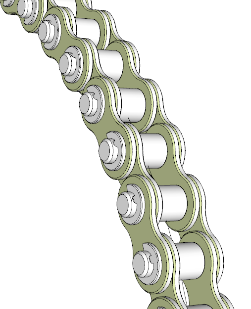
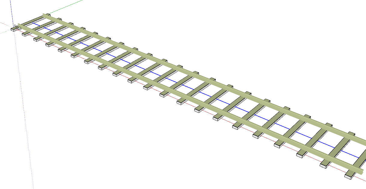
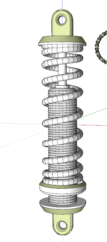
Compared to the time it would take to model these things from scratch, correcting face orientations manually is fairly trivial but it could be nice to not have to worry about that.
- Would it be possible to do something about the definition scale? As it is now, at least with objects like the adjustable sprint and bicycle wheel, the objects are scaled but the definition isn't. That means that you can get clipping and the object will disappear if you open it for editing. Perhaps creating all of the objects as components and scaling their definitions after creation would be a good option. At least in my work flow I would prefer to use components throughout because that makes later edits to things easier.
Thanks again for the tools.
- It would be nice if there were no exposed back faces. In these examples the green color is my default back face color.
-
Hi how are you.
Thanks for your plugin, it's very good.
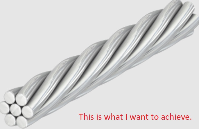
I wanted to ask you if you have any tutorial to create a cable.
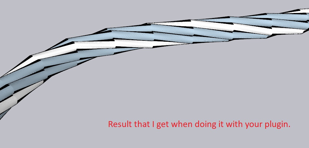
When trying to do so, many straight sections are visible.
In what you can help me, I appreciate it.
Thank you.
-
@chapalee said:
When trying to do so, many straight sections are visible.
You are using a Sketchy line style which makes the short segments visible. Either don't use a sketchy line style or weld all of the segments together and use a sketchy style that has long strokes or edit the style and turn off the edges altogether.
-
@dave r said:
@chapalee said:
When trying to do so, many straight sections are visible.
You are using a Sketchy line style which makes the short segments visible. Either don't use a sketchy line style or weld all of the segments together and use a sketchy style that has long strokes or edit the style and turn off the edges altogether.
Hello, thank you for your prompt help.
I am working with the BZ_Tools.
I don't know if I'm doing something wrong.
But it shouldn't be, because I also have to do it with straight lines and it also looks segmented.
The problem is that those segments are noticeable when rendering.
As far as you can help me, I appreciate it.
I am attaching the file where I am doing the tests.
-
You're using way too many segments for your profiles considering that they are only about 2 mm in diameter. And as I inidicated, everything is exploded after the extrusion. What looked like a sketchy line style is in reality just the excess edges being displayed. You also have a lot of exposed back faces which will likely lead to problems when you render.
Use a reasonable number of segments for the circular profile. 12 or 16 will probably be more than enough for the tiny diameter of the strands. And after getting the extrusions done correctly, weld the geometry. Eneroth Auto Weld from the Extension Warehouse will make that an easy job.
BTW, your profile says you are using SketchUp 6. Please update that to the correct version.
-
Thx all you you guys, its great to know its usefull.
@tutorialsup said:
what is the difference between Truncate and Always Z
and- in Make Roller Chain it's "Roller Tickness" & "Plate Tickness" please review the names I think it should be "Thickness"?
-
when making a face on a point in 3d space, you will need
something more, with is the up reference for me, truncate will take the closer axis and always up wel.. always z. It can differ the method depending on what your trying to. -
That should be tHickness for sure, sorry and thanks. english is my my secondary lang,a
-
@dave r said:
-
It would be nice if there were no exposed back faces.
-
Would it be possible to do something about the definition scale?
Thanks YOU
-
Sadlly I dont think I`ll be able to make sure about faces normal.. Most of those cases I dont have any reference (variable) to them so I can invert ;(
-
Those details are built on like 1000x scale... Idk for now about a setting the final scale parameter.. but will be looking for it.
for now, only bad news for you, sorry :l
-
-
I don't know enough about the code but I would expect there must be a way to ensure proper face orientation. There are other scripts that generate 3D geometry which seem to do it successfully.
As for the definition scale, perhaps you can call the "Scale defnition" command after creating the components?
I suppose TIG or Fredo6 would be knowledgeable about those things.
-
@chapalee said:
Hi how are you.
Thanks for your plugin, it's very good.
I wanted to ask you if you have any tutorial to create a cable.
When trying to do so, many straight sections are visible.
In what you can help me, I appreciate it.
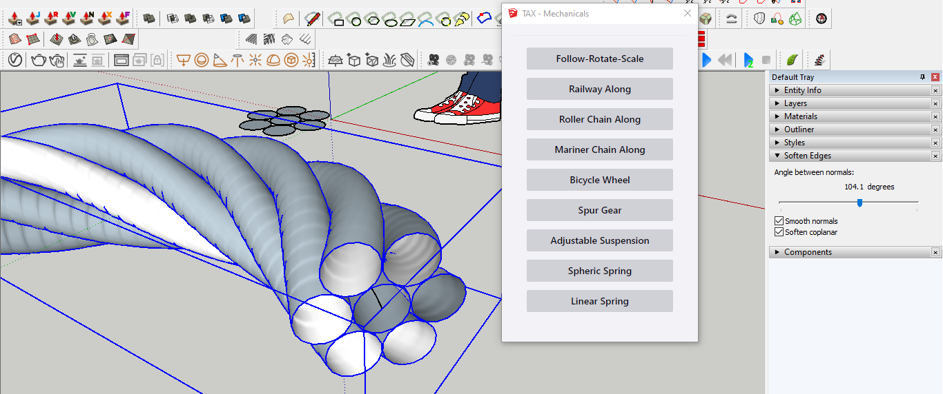
Thank you.Dave said it all, there is too much of something somewhere.
My experiment:
-
@dave r said:
I suppose TIG or Fredo6 would be knowledgeable about those things.
The way I coded it, I dont have reference to all faces.. maybe bc im still nub lol
But Im having good expectatons about resetting the final scale.Im not rlly active atm so wont be updating it very soon but lookig foward to it.
added on my to do list. -
Hey ya again guys
I've done some improvements since then
I've added some presets for mariner chain.
Planning to do the same for roller chain, spur gear and bicycle wheel.
also some minor improvements such as bug fix here and there.Presets:

About those last issues:
I've reduced the building scale, witch should fix clipping issue in most cases.
I still have to study the definition scale, thx Dave for the suggestion.
and I've a plan to fix inverted faces by doing ir manually when creating then, hopping it works.thx yall

-
Roller chain presets added:

Mariner chain presets is based on RUD's catalog
Roller chain presets is based on FENNER's catalogWhy? you may ask.
A: Bc between all I've found, their was the most complete and detailed catalogues.Let me know if you guys find any bugs.
Now planning gears and wheels presets.Enjoy

-
96 Bicycle wheel presets added: based on mixed web infos.
(Also fixed spur gear verifications.)
There’s almost 5k download! thx yall

obs: EW should also show us some stats
I’m still planning something special to celebrate it.
cya guys -
NEW UPDATE
Improved some terminology & allowed Mac users; (Thx to Trans-Galactic Express)
-
Is there possibility to make any kind of live preview of selected option? Something like JoinPushPull or Profile Builder... Selecting options without what they exactly mean is too archaic workflow for 2022.
-
@rv1974 said:
live preview of selected option?
Sure there is, but its out of my knowledge at the moment

It uses OpenGl operations to draw such things on Curviloft by Freedo or Shape Bender by Chris F.
Actually I may ask them for tips on how to make it...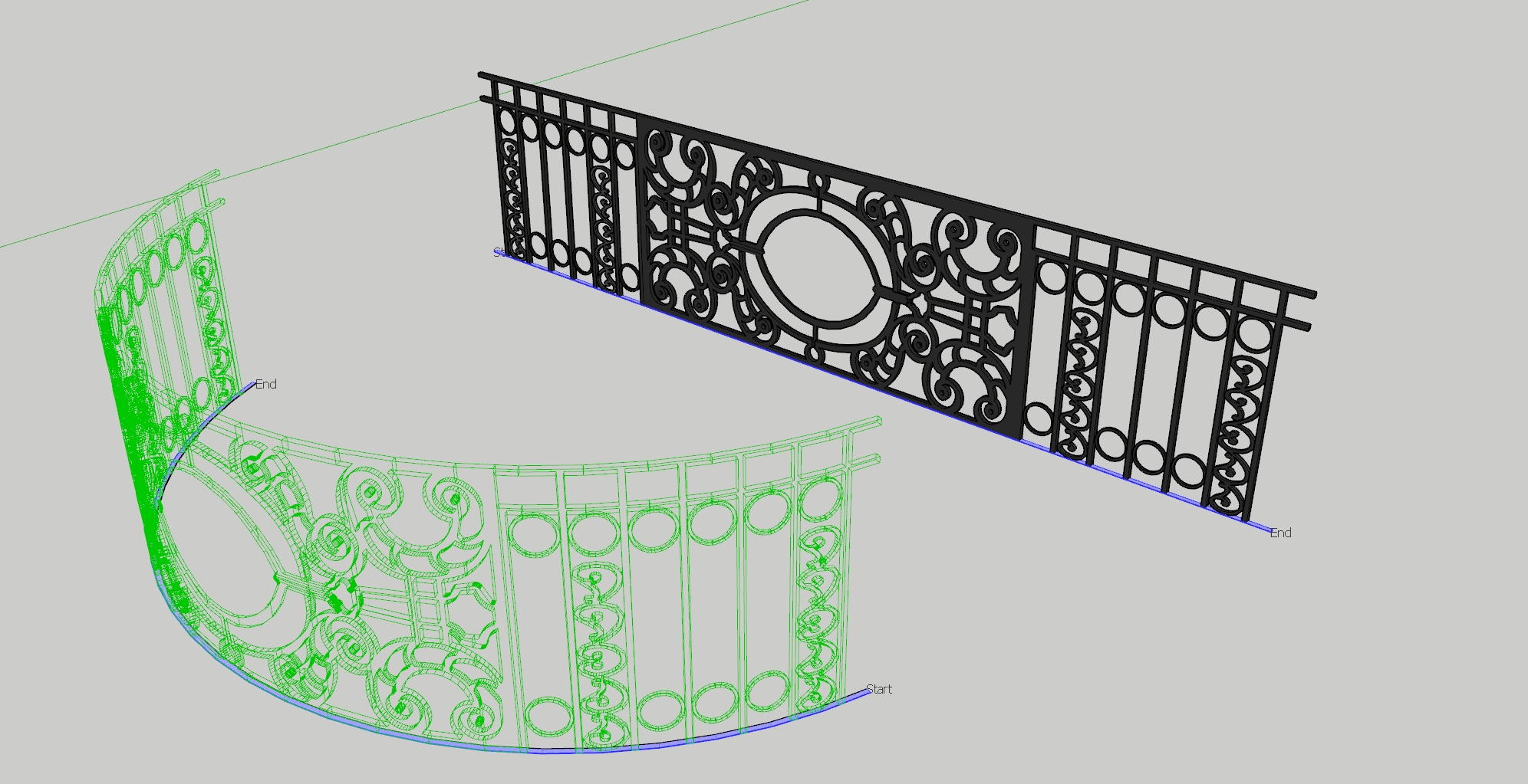
On short period, I think its better for me to focus on documentation.
My current TO DO list:
- Documentation;
- Improve notification system;
- Live preview; (maybe study OOP too);
- Street along path (with intersections).
-
Advertisement


