Wrap custom shape path around dome
-
Hi there,
Wondering if anyone knows how to do this. I want to apply a custom path shape, wrapping it around the top of a half-sphere. If you could imagine pasting a shape on top of a cylinder, in order to remove the negative space around the shape--like a cookie cutter--well, this is the same idea, only removing the negative around a domed shape, not a cylinder.
The shapes are pre-made by someone else, and complex, and would not be easy to reproduce inside SketchUp. I looked at the Tools On Surface plugin, which seems like just the thing, except it doesn't seem to let you paste in a path from somewhere else, that I can see.
Anyone have any ideas?
Thanks!
-
Please upload an example SKP file that shows what you are trying to do.
-
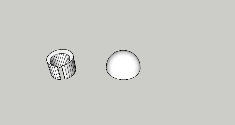
Pretty simple, just a little dome.
An example pdf created from one of the paths to "wrap" over the top of the dome.Thanks, here is a very simple dome created just to test the process with, and an example image of one of the vector shapes.
-
Just a thought but maybe Flowify...https://www.youtube.com/watch?v=xNMhUly6Ojc
-
Do you just want to drape that shape over the dome as a texture/material?
-
@dave r said:
Do you just want to drape that shape over the dome as a texture/material?
No, I want to wrap the vector path of the shape around the dome, to be able to remove the negative-space parts of the dome which fall outside the shape. The center point of the shape would be aligned with the top center point of the dome.
Thanks for the responses so far. Hope someone else maybe has an idea!
-
Hi,
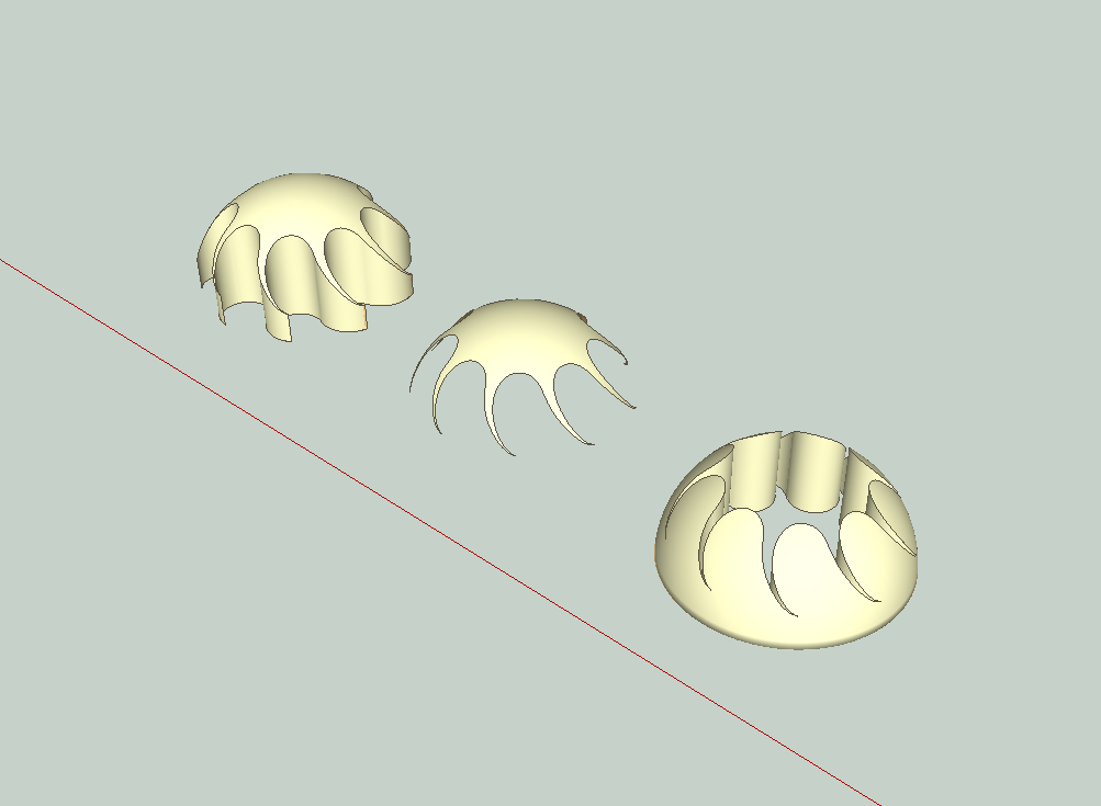
I am not sure I understand, but I wondered if your request was similar to what I'd call an extrusion with a subtraction. Are any of these shapes close?

-
@pbacot said:
Hi,
I am not sure I understand, but I wondered if your request was similar to what I'd call an extrusion with a subtraction. Are any of these shapes close?
That looks like it at least might be in the right neighborhood. How did you do it?
-
I extruded the shape (PushPull) and aligned it to the dome.
I used "solid tools" to make different subtractions, but with Make you can use "intersect faces", and erase what you don't want. I'd first align the shapes as groups, and then explode the groups so you can use the interesect command.
I also used a couple of plugins, just to make it faster. Solidsolver (not needed using intersect faces), QS Align (quickly centers the shapes, which can be done "manually"), and "addfaces" - 'cause I'm lazy (a face can be made by drawing along an existing edge of a closed shape).
-
After some delay, I'm finally getting a chance to come back to this. I can see how you're using solid tools to make the intersections/subtractions, but when I do it I'm getting a horrible jagged edge from the interacting polygons. What am I doing wrong here? This was made with solid tools > intersect, using one of the simplest shapes I need to work with.


-
I think you may need more facets in both dome and the cutting shape. Smoothing the edges doesn't change the geometry, just the appearance. (If you want the smooth appearance use the "Soften/Smooth Edges" Window. This doesn't change how the cut will look.)
-
Agreed -- but I can't figure out how, in Sketchup. Entity info (and other tools) aren't giving me that option to increase line segments.
-
@fleawig said:
Agreed -- but I can't figure out how, in Sketchup. Entity info (and other tools) aren't giving me that option to increase line segments.
You need to draw them with more segments from the beginning.
-
Aha.
These are being extruded from imported SVG files. In Illustrator, the shapes certainly look like they'd just be smooth vector curves. (And they definitely have fewer points on the curve in Illustrator than they do once imported.)pbacot, in your example you don't seem to have this problem. What am I doing wrong, any ideas?
-
Unfortunately when you import the file SketchUp will assign a number of segments (edges) to a curve that was vector curve in Illustrator. I wonder if you import at a greater scale, more edges will be assigned. I am only familiar with importing with DWG or DXF for vector information and results vary. For example SU will recognize DWG circles, and although it assigns a low resolution number of edges to circles, you can increase that.
There are plugin tools, such as "Curvizard" to re-process curves within SU. Another approach might be to make them into finer resolutions polygons before importing.
When you toggle "Hidden Geometry" under the View menu in SU. You might see better what is happening with interaction of edges and faces, that creates a jagged look. It appears there are more jaggies at the outer portion of the dome, which would make sense because the dome is probably drawn with smaller faces at the center. The cutting faces are creating longer lines across the larger faces.
-
Thanks, that's very helpful. Perhaps if I do the whole intersection operation at a larger scale, then scale down the results at the end--that could work? I'll try it out. (As well as your other suggestions.)
-
And you don't remember how you did it so smoothly in your example, do you?
-
I was looking for that file but I didn't save it. I made my own dome from circles with follow me and probably used a lot of facets in each circle probably 48s. I imported your pdf shape into CAD and exploded the pdf. The CAD produced bezier curves from it. I imported the shape to SU via dwg file, the resulting shape in SU had about 100 segments in each of the curves. That gives an idea of how many edges you need.
-
@fleawig said:
Thanks, that's very helpful. Perhaps if I do the whole intersection operation at a larger scale, then scale down the results at the end--that could work? I'll try it out. (As well as your other suggestions.)
That's a good idea, but still the segments have to be greater [in number]. Importing a larger file MIGHT give you better curves, but the dome likely has to have more facets and scaling one up alone won't do that.
It may be a good idea to do the trimming at a larger scale because SketchUp has difficulty creating very small faces. It's OK however to scale down larger faces once created.
Advertisement


