RCP and lighting plan
-
Hi pros!
I'm completely new user to Sketchup and a new member in sketchucation, so you can call me newbie

moving from Chief Architect + AutoCAD to Sketchup and found alot of amazing tutorials almost about everything in Sketchup.However Layout is different story - very little help from Sketchup itself. Youtube has some tutorials to offer (most of it are very old)
There is one part that I can not find any info is Reflected ceiling plan and lighting plans.
Please give a newbie some information on how you guys manage it. Here is what I think:
Make reversed cutsection and import it to layout, then somehow you align 2d symbols and lay on top of lights? annotate them and hide lights? is this best way or it's not a way at all:)Would be good to have some tips from Nick Sonder, somehow he managed to slip through and didn't revealed secretes how he manages that:)
Thank you for all your input.
Simonas. -
I'm sure if you look through the many Nick Sonder YouTube entries there's stuff about RCPs, line work and use of scrapbook elements etc...
e.g. https://www.youtube.com/watch?v=LAZshFN0I-o about 40 seconds in RCP... then at ~3mins he explains RCP some more...
Nick is well worth watching... -
I use this plugin that CadFather made... it has a bottom view to go along with all the top, side, front etc. Don't know if Bottom view is a native command or not. But I use it to show my reflected ceiling plan, I copy my entire floor plan scene over and then hit the bottom view button. you'll have to add another section cut, I copy the current section cut and rotate it 180 just like it was an object.
Have you downloaded my symbols pack or my layout template with built in Su model?
My list of architecture plugins and extensions...
http://sketchucation.com/forums/viewtopic.php?f=323%26amp;t=59471%26amp;p=541170#p541170My scrapbook of symbols and architectural aids.
http://sketchucation.com/forums/viewtopic.php?f=40%26amp;t=49829My blank client folder template.
http://sketchucation.com/forums/viewtopic.php?f=18%26amp;t=59229 -
But remember that a standard REFLECTED Ceiling Plan is looking downwards, NOT upwards.
I can never see the issue... ALL plans look downwards, even for ceilings, you rarely make a plan looking upwards
-
you make it look upwards to see the reveal and details that you're supposed to see. Then you just scale -100/% up or side to side and it reverses it while keeping it locked to the updating reference file.
-
@pbacot said:
TIG what do you mean you can never see the issue?
A floor plan looks downwards - it just a convention - we could just as easily look 'upwards' !
The obvious way of portraying a ceiling plan is also by looking 'downwards'.
[At least to my mind]
So a "RCP" is a by now 'misnomer'If you want an 'elevation' of a ceiling looking upwards it's something quite different.
Only applicable if you were giving detailed instructions to Michael Angelo for the ceiling of the Cistine Chapel
In the UK we'd now call it a 'ceiling-plan', just like a 'floor-plan', and you would always look 'down'.
-
I think you're missing the point... a reflected ceiling plan does look down. but when you cut a section above it you have lots of things getting in the way of a proper plan view.
so you set the section to look upwards (reflected) and then mirror the referenced sketchup viewport using the scale tool. this gives you the view downward with the reflected detail.
-
I would remove the "reflected" too. It's just that it isn't a real "picture" or view if you looked up at the ceiling (you can't look down through the ceiling and see the surface).
The reason it is done this way is I believe people reading the floor plan would get lost if they looked at ceiling plan looking upward. Also pre-mylar it would be easier to trace one plan off the other, then in 2d CAD it is really easier to relate or superimpose elements from the two plans when creating the drawings.
Yes, anyway plans are very symbolic way of representing a building, less pictorial than elevations. If you leave the "reflected" off the drawing title in the US, someone is sure to correct you!
-
I did not know that. You can just flip reference. Rick talks about making a separate SU file with an import of the main model scaled 100% but that doesn't seem necessary (now at least) if you can just flip it in LayOut????
[edit; On further recall, I think he does that so he can have shadows on the ceiling in SketchUP.]
TIG what do you mean you can never see the issue?
-
Thanks Tig!
A reflected ceiling plan is exactly as it sounds. It is as though you are looking down at the floor plan with a mirror for the floors surface.
I keep a separate RCP file that is used for both the architectural RCP and the lighting plan. It simply has my main structure model as a reference scaled at -1. The model is never edited in this file and the file is only used to create the specific scenes for the differenct RCP's. Then you simply cut a section looking down at the ceiling. Funny timing as I am doing a lighting plan right now.
-
@unknownuser said:
Thanks Tig!
A reflected ceiling plan is exactly as it sounds. It is as though you are looking down at the floor plan with a mirror for the floors surface.
I keep a separate RCP file that is used for both the architectural RCP and the lighting plan. It simply has my main structure model as a reference scaled at -1. The model is never edited in this file and the file is only used to create the specific scenes for the differenct RCP's. Then you simply cut a section looking down at the ceiling. Funny timing as I am doing a lighting plan right now.
But after you put it into Layout, how to you align your 2d scrapbook symbols on top? Try to find a centre of a recessed light and put 2d symbol?Later do you hide 3d lighting models? And if something changes - like you move recessed light, you do this in 3d model, then you have to move 2d symbol as well?
-
When I was younger [a long time ago!] plans of ceilings were always made looking 'downwards'.
Here in the UK they were then sometimes called 'Reflected Ceiling Plans', but over the years this convention has changed to 'Ceiling Plan', just like we'd call a 'Floor Plan', 'Framing Plan'' or 'Roof Plan'.
You are always looking downwards in these projections - so to me the 'Reflected' adjective is confusing as it's only ever applied to ceilings, and although I realize that in the US it's a more common nomenclature, I'd not expect an American to think a 'ceiling plan' would be looking drawn upwards ??A plan is a section looking directly downwards: a section is a cut through a volume, usually showing what is visible as if the viewer is on that plane looking into the volume, you'd never expect it to show what is behind the viewer's position !
A elevation is a section cut too - if it is drawn outside of the volume it shows the external faces visible looking perpendicular from that 'plane'; if it is drawn inside a volume then the internal surfaces of walls etc are seen.
A ceiling plan is slightly unusual in that its plane is effectively on the surface of the ceiling looking down, but that's no more confusing a convention than [usually] cutting a floor plan's section plane at 5' above the floor surface and looking down, rather than locating it on the actual floor surface itself.
A steelwork plan usually cuts through columns at ~5' and then if its at ground level it often shows foundations [dotted] etc but nothing above that; if its for upper floors then it shows the beams for that floor, but with no floor build up; and if it's for the roof steel, then it shows those looking down, with no roof-finish obscuring them. So in many ways the ceiling-plan convention is the corollary of these - if its to show what is below the ceiling [dotted-walls, dotted-openings, and things on its surface, like moldings, lights etc], which is one type [a 'Ceiling Plan' including the adjective 'Reflected' if you must], and if it is to show what is above the ceiling [e.g. ducts, downstanding-beams etc - things below the structural floor-slab that is over it [e.g. common in offices etc] then it's another [perhaps a 'Ceiling Void Plan'] - and sometimes these are combined.I don't expect that anyone thinks that a horizontal section cut through a room should look upwards ?
It's useful to sometimes see doorways or openings below and even light fittings which are actually below the ceiling. -
Well, I thought my solution was ingenious... If I do say so myself.

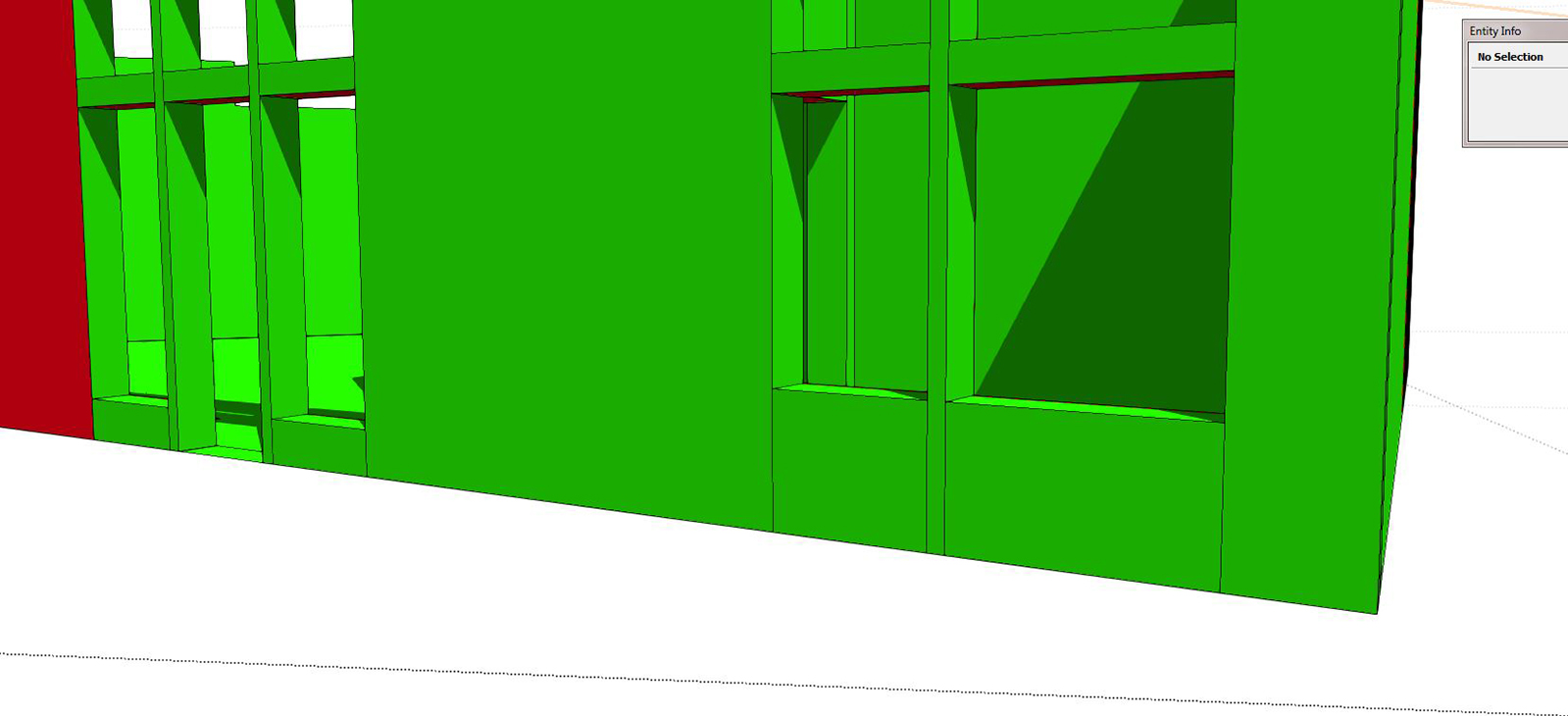
I've always had a hard time with cutting my floor plan sections too... You need them to cut through every opening, but sometimes that just doesn't work out. That's why I leave my openings cut floor to ceiling.
as you see in this image, my floor to ceiling line work allows the cut to be anywhere and still show and opening, albeit less detailed than one cut through a window.
-
anyone has something to say about 2d symbols and how you align them?
-
I started putting my symbols inside of my components and putting them on another layer. I can turn them on and off and they are already with the doors and windows and fixtures.
-
@asimonas said:
@unknownuser said:
Thanks Tig!
A reflected ceiling plan is exactly as it sounds. It is as though you are looking down at the floor plan with a mirror for the floors surface.
I keep a separate RCP file that is used for both the architectural RCP and the lighting plan. It simply has my main structure model as a reference scaled at -1. The model is never edited in this file and the file is only used to create the specific scenes for the differenct RCP's. Then you simply cut a section looking down at the ceiling. Funny timing as I am doing a lighting plan right now.
But after you put it into Layout, how to you align your 2d scrapbook symbols on top? Try to find a centre of a recessed light and put 2d symbol?Later do you hide 3d lighting models? And if something changes - like you move recessed light, you do this in 3d model, then you have to move 2d symbol as well?
The only lights I model in SU, are typically decorative fixtures like pendants and sconces. All the general lighting like cans, I only add when I render in LumenRT. Any lighting that I add in SU is on its own layer and turned off for the CD scenes for LO. For the RCP in LO, I use my lighting scrapbook with symbols for various lighting types. I simply place them on the ceiling in an appropriate pattern. It's very easy to copy in LO in a defined grid & spacing, since you can set the insertion point of any element, anywhere you like.
-
I think inserting models, scrapbook items, copy and pasting all of the insertion tools confuse autocad converts a bit when the first come on board. Something odd about the selection of the point of use.
-
@unknownuser said:
@asimonas said:
@unknownuser said:
Thanks Tig!
A reflected ceiling plan is exactly as it sounds. It is as though you are looking down at the floor plan with a mirror for the floors surface.
I keep a separate RCP file that is used for both the architectural RCP and the lighting plan. It simply has my main structure model as a reference scaled at -1. The model is never edited in this file and the file is only used to create the specific scenes for the differenct RCP's. Then you simply cut a section looking down at the ceiling. Funny timing as I am doing a lighting plan right now.
But after you put it into Layout, how to you align your 2d scrapbook symbols on top? Try to find a centre of a recessed light and put 2d symbol?Later do you hide 3d lighting models? And if something changes - like you move recessed light, you do this in 3d model, then you have to move 2d symbol as well?
The only lights I model in SU, are typically decorative fixtures like pendants and sconces. All the general lighting like cans, I only add when I render in LumenRT. Any lighting that I add in SU is on its own layer and turned off for the CD scenes for LO. For the RCP in LO, I use my lighting scrapbook with symbols for various lighting types. I simply place them on the ceiling in an appropriate pattern. It's very easy to copy in LO in a defined grid & spacing, since you can set the insertion point of any element, anywhere you like.
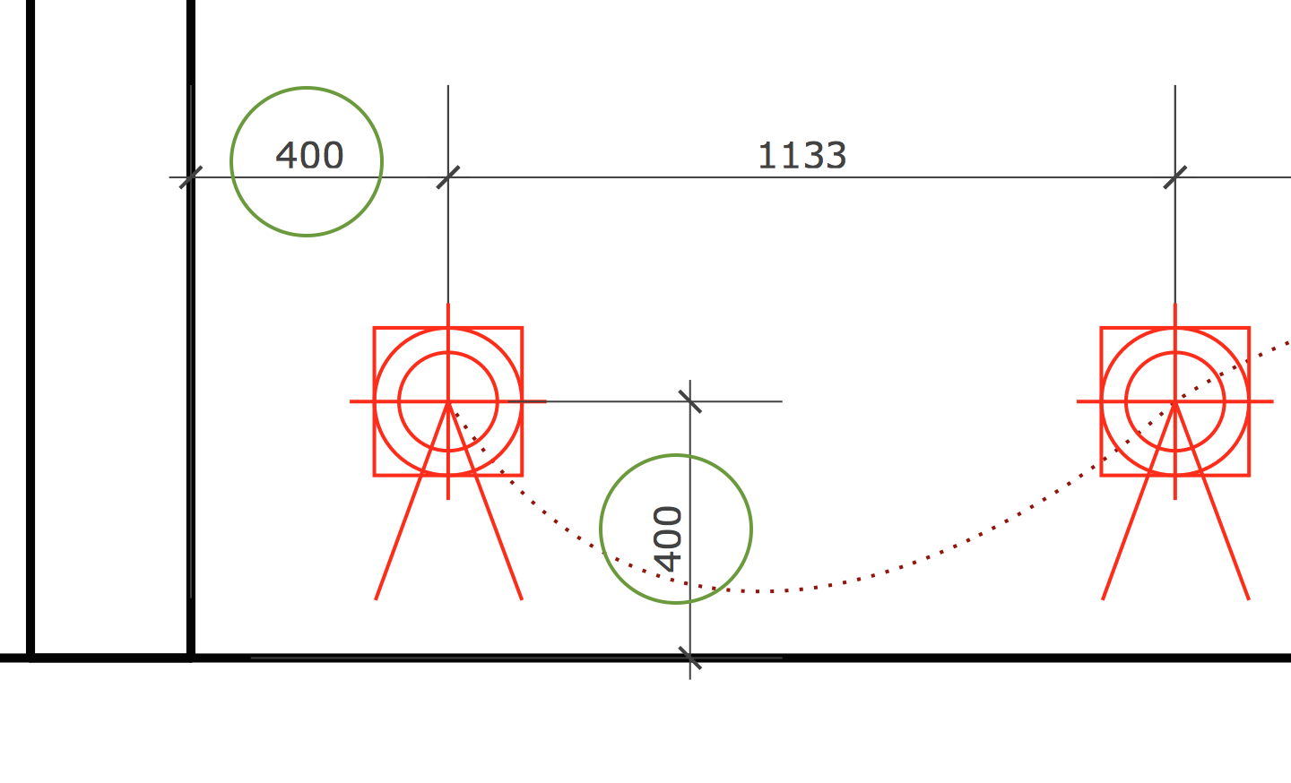
Thanks Nick, but how you adjust symbol in LO without having real 3D lamp model in precise location in SU?
For example: here I have screenshot - first left light must be 400mm from left and 400mm from bottom wall.
How you would measure it in LO? I would love to have Layout tape measure where you could choose scale and draw guide lines so you know exactly where to place symbols. How do you find that point?
-
So we have two very different approaches:Symbols in SketchUp and symbols in LayOut.
-
Asimonas, I am never concerned about the exact position to the MM like that. The reality is, during construction, there will be flux in that location. For instance, if you are positioning lights in a floor cavity, the framing will dictate the locations more than the lighting plan. What I am concerned about is general placement, pattern and symmetry about a room. If you want to set a lighting layout that precise, you need to then make sure you modify the framing to allow that to work, or suspend a ceiling That can get very expensive. For decorative fixtures that are set over something like a sink or centered about a stair, I will first place the symbol on the floor plan or power signal plan, then cut/paste it onto the RCP. Since I setup my RCP with the exact orientation as the floor plan, this is very easy.
Hello! It looks like you're interested in this conversation, but you don't have an account yet.
Getting fed up of having to scroll through the same posts each visit? When you register for an account, you'll always come back to exactly where you were before, and choose to be notified of new replies (either via email, or push notification). You'll also be able to save bookmarks and upvote posts to show your appreciation to other community members.
With your input, this post could be even better 💗
Register Login


Advertisement