Thick and thin lines
-
I think I still don't understand what makes a line thick or thin by default (I'm not employing any special settings). I get the basic principle that a line with a "loose" end will be thick, and will become thin - ie become a proper edge - when it is part of a completed polygon.
In the current case, I'm only doing a two-dimensional diagram, so viewpoint aspects of thick and thin shouldn't be relevant. I have a standard model called 2D canvas, which is just a white rectangle. I draw everything 2D on that surface, avoiding (I hope) any non-coplanar lines.
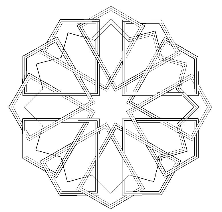
But lines still turn up thick when I think they should be thin and areas are not properly enclosed as faces, allowing colouring. Attempts to colour some of the apparently enclosed areas which have thick-line boundaries result in the colour leaking out over the whole canvas.
Assiduous erasing and redrawing of lines sometimes succeeds in making them thin when they were previously thick, but this doesn't always work.
What am I doing wrong or failing to understand and how do I ensure all lines are thin and all areas properly enclosed?
I append a screen-grab of the incomplete drawing. If my mistakes are not obvious from that, I will upload the model.
Thanks in advance.
-
Lines and Edges are synonymous in drawing 2d...
The current Style determines how edges are displayed [see Styles > Model-Styles > Edit].
From your point of view there are two that need to be set/ticked.
Edges and Profiles.
The Edges setting is the number of pixels that the general edges show in, i.e. an edge having 2 faces.
The Profile setting is the number of pixels an edge shows in - if its an edge with no faces at all or an edge with one face [i.e. on a perimeter of a face], it also ensures that any curved surfaces in 3d still display something even if the surface arcs away from the camera.Coplanar edges which form a continuous loop will automatically get a face.
Additional edges can split a face into smaller facets if possible.
The inner edges that have 2 faces will show in the Edge Style, the outermost ones or unfaced edges will be shown as Profiles...Sometimes edges do not split a face as expected.
If you select the geometry [faces/edges] in question and right-click > context-menu > Intersect... they will usually split as much as they can.
Obviously an edge that has a lone-vertex cannot split anything and will show as a 'Profile'...
Hello! It looks like you're interested in this conversation, but you don't have an account yet.
Getting fed up of having to scroll through the same posts each visit? When you register for an account, you'll always come back to exactly where you were before, and choose to be notified of new replies (either via email, or push notification). You'll also be able to save bookmarks and upvote posts to show your appreciation to other community members.
With your input, this post could be even better 💗
Register Login


Advertisement