Door schedule Layout 2013
-
Any tips about how to make a door and window schedule? Tried inserting an .rtf file which is maybe okay until I try to edit the text in Layout at which time the Text palette looks like a pinball machine for thirty seconds or so before making the change. Tried copy and paste into a text box...same strange behavior. Seems to be no way to insert a table. Did a screen capture of the table from the word processor, but that makes a bigger file. Windows 8, i7 Quad 3.6GHz; 16gb ram; Quadro 600; Intel 335 SSD.
Edit: Insert an .rtf, work on it more in WP, insert the updated file, Layout retains the old one. Must Save as... with a new name to insert the update.
-
My method is to take each window and door component and make a copy and line them up for an elevation. Then I dimension and show a schedule for door and window symbols.
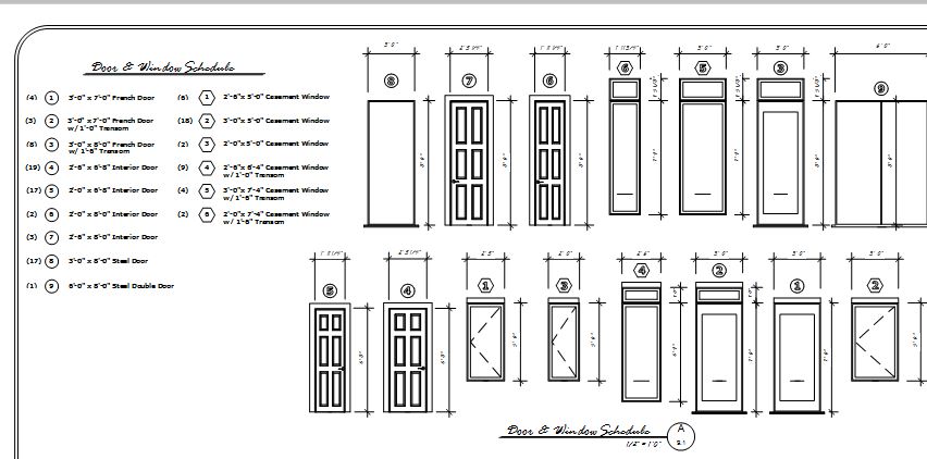
if you notice the symbol above the windows and doors, that is inside the component. It hides inside the wall in 3D and then I have another one on the floor level in the doorway.
-
I have just noted on another thread: I have luck printing to pdf then insert the pdf. Thereafter keep the same process and update the pdf in LO. Keep a folder with such pdfs for the project. Always print (overwrite) to the same file and update in LO. You don't have to position it or anything. Haven't tried rtf. Be sure to save your original WP file so that it reflects what you output in the pdf. Update is instantaneous.
-
Regarding editing rtf files, don't edit them in LayOut. Right click on the text box and choose Edit in Text Editor. Word or whatever editor is the default to open RTF files will open. Make your edits and save the file. It will be updated in LO automatically.
If you do decide to replace the RTF file with a different one, Make the new RTF file. It can have the same name as the original. Go to File>Document Setup>References. Select the line for the RTF file, unlink it and then relink to the new file.
-
If you are actually creating a diagramatic schedule as Krisidious shows, just draw them raw in LO so you can edit how you like. Will take 1/10th the time of doing it in SU and dragging the model in and stuffing around!
-
@krisidious said:
if you notice the symbol above the windows and doors, that is inside the component. It hides inside the wall in 3D and then I have another one on the floor level in the doorway.
Would love to learn more on how this works...
-
-
Nice, figured it out with some testing.
Clever.Might have to do something similar with timber sizing... hmmm.
-Mike
-
Cool idea.
I expect there's a lot more of that sort of thing that could be done with nesting components and things like 3D text.
-
well, it's really simple.
I take all my doors and windows in a model and make a copy of the component and then line them up. (this is after design.) Then I use the 3D text tool to create the number/symbol geometry... 1 vertical and one horizontal on the floor level. I put all of this geometry on a layer called symbols, so that I can turn it on and off when needed. The vertical symbol is placed about a foot above the geometry within the door or window component. This way it is inside of the wall and not seen in 3D perspective views.
examples


-
added plan views.
-
I thought I would go through my method for window schedules using components, excel and tables and see if anyone has any tips to streamline the process. The method is similar to the one previously mentioned, however it uses the new table referencing in SU 2017.
-
Build windows as components and place where you want them in the building.
-
Create copy of component windows and place them (nicely lined up) somewhere else in your model. Create scene.
Tip: Be sure to place them where they will not obscure other scenes.
Tip: You can use a section line to cut out an area of the model in certain scenes. I have done this before when my copy of components was in the way of my elevations of the main building.-
Add dimensions and information into PHPP (This example was a passive house).
-
Reference cells from PHPP spreadsheet into window schedule spreadsheet.
-
Insert window schedule spreadsheet into LO drawing. (Make auto update as it takes no time to render).
-
Insert SU model and select scene where you set up window copy components.
-
Hello! It looks like you're interested in this conversation, but you don't have an account yet.
Getting fed up of having to scroll through the same posts each visit? When you register for an account, you'll always come back to exactly where you were before, and choose to be notified of new replies (either via email, or push notification). You'll also be able to save bookmarks and upvote posts to show your appreciation to other community members.
With your input, this post could be even better 💗
Register Login


Advertisement